2024-07-12
한어Русский языкEnglishFrançaisIndonesianSanskrit日本語DeutschPortuguêsΕλληνικάespañolItalianoSuomalainenLatina
1-Electrolytic capacitor ripple current problem
This value cannot be exceeded in application. Generally, this parameter exists in electrolytic capacitors and corresponds to ESR.
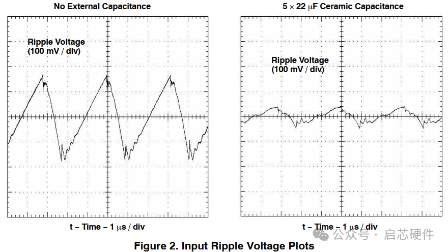
Relationship between measured ripple voltage and number of capacitors
2- Ripple current
The relationship between ripple current and ESR is very close. At the same time, ripple current can cause self-heating of capacitors on ESR. If the heating is serious, it will also affect the service life of the capacitor. As the frequency increases and the ESR decreases, the ripple current is easier to flow, so the specification generally gives the rated ripple and frequency correction factor.
Ripple current refers to the alternating current flowing in a capacitor, which is usually caused by the changes in the AC signal generated by the power supply. In power supply systems, especially switching power supplies or other power supplies with pulse characteristics, capacitors are affected by pulsating or ripple currents from the power supply.
Specifically, ripple current is the AC component flowing through the capacitor, and its frequency is usually related to the switching frequency of the power supply or other system operating frequency. This ripple current is caused by the voltage changes caused by the switching operation of the power supply, and the capacitor is used to smooth this voltage change.
In a power supply, the presence of ripple current may affect the stability and performance of the system. Therefore, selecting the appropriate capacitor and understanding the ripple current capacity of the capacitor are important considerations when designing a power supply system. Generally, capacitors with appropriate specifications can effectively reduce the ripple in the power supply and improve the stability and performance of the system.
Ripple current is the AC current flowing into the capacitor. Ripple current makes the capacitor heat up. Excessive ripple current will lead to excessive temperature rise, causing the temperature of the capacitor core to exceed its maximum allowable temperature and quickly damage it. Even if it works close to the maximum allowable core temperature, the expected life will be greatly shortened. The maximum allowable ripple current depends on whether the load life index of the capacitor can be met. For aluminum electrolytic capacitors working at the maximum allowable core temperature, the typical value of its load life index is 8000 to 10,000 hours, which is about one year. For most applications, this time is too short. Therefore, it is not allowed to work at the maximum allowable core temperature, and the selection calculation should be carried out according to the application life requirements.
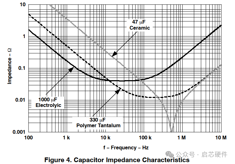
3-Impedance Problem
4- Hardware design derating application specifications:
Listed below are some commonly used derating parameters in the application of electrolytic capacitors, which can be used as a reference when designing circuits.
Rated voltage: Select a voltage greater than 1.25 times the maximum bus voltage
Capacitor capacity: Under rated system conditions, the bus voltage fluctuation does not exceed ±5%, and the capacity is calculated
Ripple current: Under rated system conditions, the ripple current shall not exceed 85% of the rated value.
Self-heating temperature: generally not more than 5℃
Capacitor life: Evaluated according to system life requirements

I have devoted myself to the research of technology for more than 30 years. I am proficient in various languages such as Java, Linux, JavaScript, PHP, CSS, etc. I have made many contributions in the field of open source. I have established a developer documentation site to share some problems in technology development for everyone to read.
