2024-07-12
한어Русский языкEnglishFrançaisIndonesianSanskrit日本語DeutschPortuguêsΕλληνικάespañolItalianoSuomalainenLatina
Statement: The article referencesSystem architectTutorial (Second Edition)", if there is any infringement, I will modify and delete it immediately.
A system that uses communication lines to connect geographically dispersed computer systems and communication equipment with independent functions in different forms, and relies on network software and communication protocols to achieve resource sharing and information transmission.
In the 1960s, a remote online system centered on a single computer was used to transmit information.
In the 1960s and 1970s, multiple hosts were connected through communication lines to share resources with each other.
From the late 1970s to the 1990s, there was an open and standardized network with a unified network architecture that complied with international standards. Two important architectures emerged during this period: the TCP/IP architecture and the OSI architecture of the International Organization for Standardization.
From the 1990s to the present, local area networks have matured, optical fiber and high-speed network technology have emerged, and the Internet, represented by the Internet, has developed.
A communication method that uses data transmission technology to transmit information between two communication nodes according to a certain communication protocol. The transmitted information is expressed in binary data form. Features: Related to telematics.
PS: Three major communication services: telegraph, telephone, and computer network
Sharing of hardware resources, software resources, and data resources
MIS
Large tasks are divided into small tasks that are processed by different computers and then solved centrally.
It means that the workload is evenly distributed to each computer system on the network. The network center is responsible for distribution and monitoring. When a computer is overloaded, the system automatically transfers the workload to a computer system with a lighter load.
The rate at which hosts or communications devices connected to a computer network can transmit data over a digital channel.
1) Refers to the channel width of a signal. The bandwidth of a signal indicates the frequency range occupied by the various frequency components contained in a signal. The unit is Hertz (kHz, MHz, Gigahertz, etc.)
2) Computer network: Bandwidth refers to the ability of the network's communication lines to transmit data. Network bandwidth refers to the "maximum data rate" that can pass from one node to another in the network per unit time. Unit: bits per second, b/s
The amount of data that passes through a network (or channel, interface) per unit time. Limited by the network bandwidth or network rated rate.
Sometimes throughput is also expressed in bytes or frames transmitted per second.
The time it takes for data (a message, packet, or even bit) to travel from one end of a network (link) to the other.
It is divided into: sending delay, propagation delay, processing delay, queuing delay, etc.
The time from when the sender sends data to when the sender receives confirmation from the receiver (the receiver sends confirmation immediately after receiving the data).
Channel utilization: The probability that a channel is being used (data is passing through it), expressed as a percentage. A completely idle channel has a utilization of zero.
Network utilization: The weighted average of channel utilization across the entire network.
The world's second largest network after the global telephone network
Information transmission: The process by which the source and destination send and receive information through a channel.
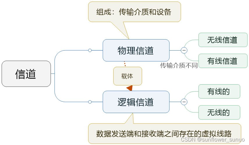
1) Channel is the channel for information transmission
2) The transmitter receives the information sent by the source, encodes and modulates it, converts the information into a signal suitable for transmission on the channel, and sends it to the channel.
3) The receiver is responsible for receiving information from the channel, demodulating and decoding it, and restoring the information to the host. Not all frequency signals can be transmitted through the channel. The frequency range is the bandwidth of the channel.
Calculate channel capacity: the maximum transmission rate of the channel
C=B*log2(1+S/N)
C: channel capacity, b/s
B: signal bandwidth, Hz
S: Average signal power, W
N: average noise power, W
S/N: signal-to-noise ratio, dB (decibel)
To increase channel capacity, you can use a larger bandwidth to reduce the signal-to-noise ratio, or a smaller bandwidth to increase the signal-to-noise ratio.
Transmitter signal processing: source coding, channel coding, interleaving, pulse shaping, and modulation.
Receiver signal processing: demodulation, sampling decision, deinterleaving, channel decoding, source decoding.
Analog signal - analog-to-digital conversion - compression coding (removing redundant information) - digital signal
Redundant information is added to facilitate error detection and correction at the receiving end.
In order to solve the problem of channel decoding errors caused by continuous bit errors, interleaving scrambles the data order after channel coding according to a certain rule, and restores the data order through interleaving before decoding at the receiving end.
To reduce bandwidth requirements, the transmit data is converted into a suitable waveform.
The process of carrying information onto a high-frequency carrier signal that meets signal requirements.
Simultaneous transmission of multiple data channels requires multiplexing and multiple access technology.
Refers to the technology of transmitting multiple data channels simultaneously on one channel.
A technology that transmits multiple user data simultaneously on one line and separates the data of multiple users at the receiving end.
A computer group (i.e., a communication network) that connects several computers via transmission media within a limited geographical area. A local area network is a closed type.
With the central node (control center) as the center, it is connected to the center through connecting lines. A node must pass through the central node to transmit data.
Advantages: fast transmission speed (any two nodes only need two steps to communicate), simple network structure, easy to build a network, easy to control and manage
Disadvantages: low reliability, poor network sharing capability, once the central node fails, the entire network will fail
Features: Low network cost and simple structure. No loop is generated between any two nodes, each link supports bidirectional transmission, node expansion is convenient and flexible, and it is easy to inspect the link path.
Disadvantages: Any non-leaf node link failure will affect the entire network system.
Each node device is connected to a bus. All node devices transmit information through the bus.
A bus failure will affect the communication of each node.
Each node is connected by a communication link that connects end to end to form a closed loop.
Each device has equal status and information flows in a fixed direction.
Any node failure will lead to physical paralysis, which is not conducive to expansion, long system response delay and low information transmission efficiency.
There is a communication link between any nodes. The failure of any node does not affect other nodes.
Complicated wiring, high construction cost, and complex control methods
Ethernet frame: A data packet on an Ethernet link, with the following structure:
| DMAC | SMAC | Length/Type | DATA/PAD | FCS |
DMAC: MAC address of the destination terminal
SMAC: Source MAC address
Length/Type: 2 bytes, value greater than 1500 indicates the type of data frame; less than 1500 indicates the length
DATA/PAD: Specific data, no less than 64 bytes (if less than 64 bytes, additional padding is required)
FCS: Frame Check Field
Purpose/Reason: To avoid data transmission conflicts on the link when a node has sent the last bit of a data packet but the first bit has not yet been transmitted to a node farther away and mistakenly believes that the line is idle.
No strict restrictions, but affected by line quality, signal attenuation, etc.
Purpose: Prevent frame loss when the device is blocked.
It consists of a central node (HUB) and several peripheral nodes. Centrally controlled communication.
No specific application.
Between cities, countries or countries
A WAN consists of a communication subnet (consisting of communication node devices and the links connecting these devices) or a resource subnet (a collection of devices and their software that implement resource sharing functions in the network).
1) Data communication services, supporting users to exchange information over long distances using computers;
2) Wide coverage, long communication distance, and no fixed topology of the WAN
3) The telecommunications department or company will be responsible for the assembly, management and maintenance, and provide paid communication services to the whole society.
Networks established in a single city
3 layers: core layer, aggregation layer and access layer
The simplest network device, data received from one port is forwarded to all other ports, regardless of whether the system connected to the port is ready. One port is designated as an uplink port, which can be used to connect to other hubs or routing devices.
LAN interconnection equipment, located at the physical layer of the OSI system.
The data link layer of the OSI system.
The data link layer of OSI. It provides an exclusive forwarding channel for any two network nodes connected to the switch. It has the functions of automatic addressing and switching, avoiding port conflicts, and improving network throughput.
The network layer of OSI. Usually used for wide area networks or the interconnection between wide area networks and local area networks.
Hardware firewall: The firewall program is built into the chip.
From low to high layers: physical layer, data link layer, network layer, transport layer, session layer, presentation layer and application layer
The same layer provides protocols, and the upper and lower layers provide services
TCP/IP protocol suite: Internet Protocol IP, Transmission Control Protocol TCP, User Datagram Protocol UDP, Virtual Terminal Protocol TELNET, File Transfer Protocol FTP, Email Transfer Protocol SMTP, Online News Transfer Protocol NNTP, Hypertext Transfer Protocol HTTP
| ISO/OSI Model | TCP/IP Model |
| Application Layer | Application Layer |
| Presentation Layer | |
| Session Layer | |
| Transport Layer | Transport Layer |
| Network layer | Internet Layer |
| data link layer | Network Interface Layer |
| Physical Layer | Hardware Layer |
Hub function; relay function; bridge function; collision domain isolation function
A switch is a network device that can encapsulate and forward data packets based on MAC address identification.
Forwarding path learning; data forwarding; data flooding; link address update
Spanning Tree Protocol (STP): Solving Link Loop Problems
Receives a data packet from a network interface and determines the next address to be forwarded based on the destination address of the datagram.
Routing protocol: A protocol that specifies how packets are forwarded.
Classification:
Routing protocols running in an autonomous system (AS)
Routing protocols between ASs
Including: network demand analysis, feasibility analysis, analysis of existing networks (when optimizing and upgrading existing networks)
Design a solution that can solve user problems, including: determining the overall network goals, determining the overall design principles, designing the communication subnet, selecting equipment, and designing network security.
Including: project implementation plan, network design acceptance, equipment installation and debugging, system trial operation and switching, user training, etc.

I have devoted myself to the research of technology for more than 30 years. I am proficient in various languages such as Java, Linux, JavaScript, PHP, CSS, etc. I have made many contributions in the field of open source. I have established a developer documentation site to share some problems in technology development for everyone to read.
