2024-07-12
한어Русский языкEnglishFrançaisIndonesianSanskrit日本語DeutschPortuguêsΕλληνικάespañolItalianoSuomalainenLatina
Table of contents
This procedure is a revision of the “Wind Power Plant with Low Carbon Characteristics Considered”Power SystemsThe method of "Source-Load Multi-Time-Scale Scheduling Method" was reproduced, but not completely. Only the day-ahead part was done, and it was improved and upgraded to an electric-thermal integrated power supply microgrid system on the basis of the above, without considering the node system.
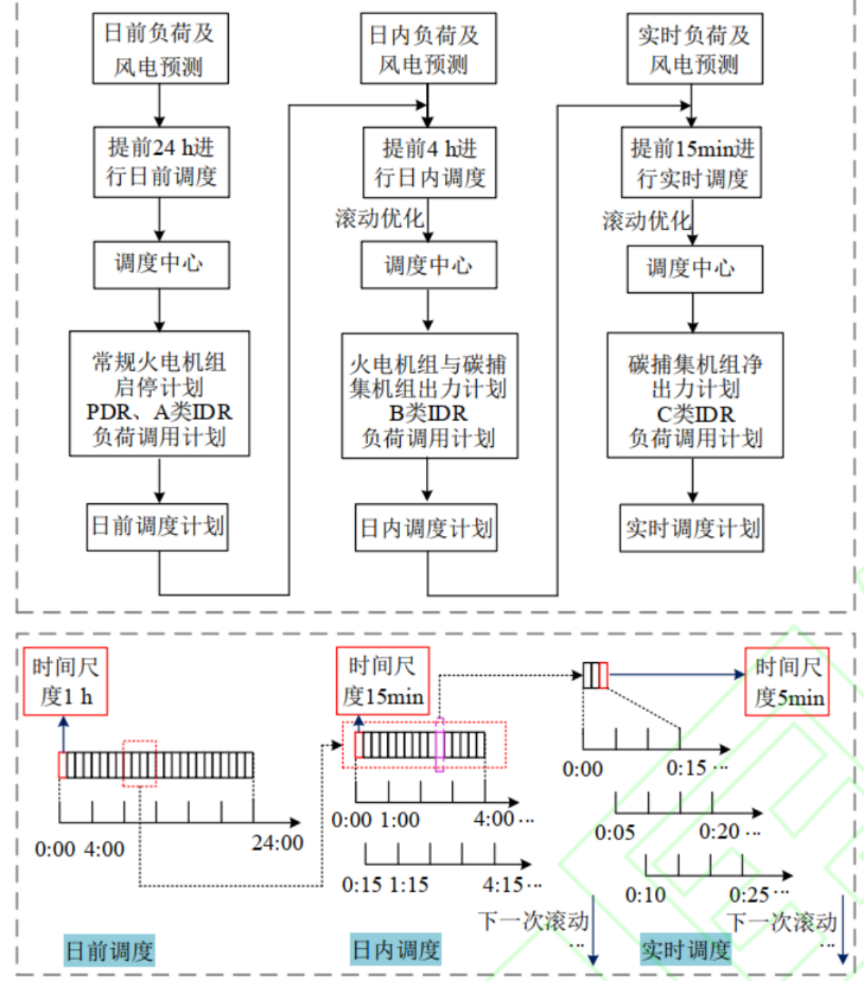
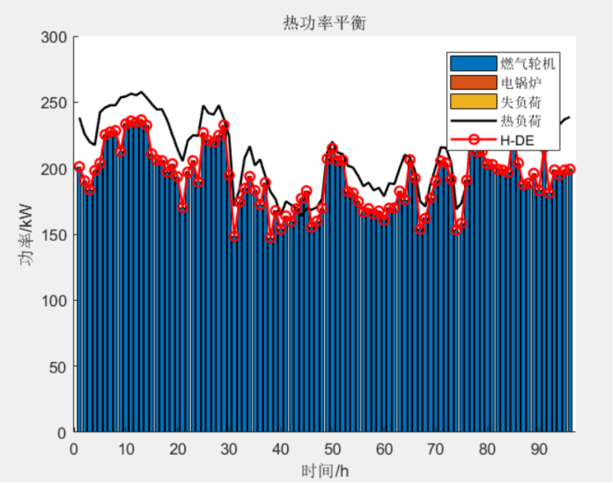
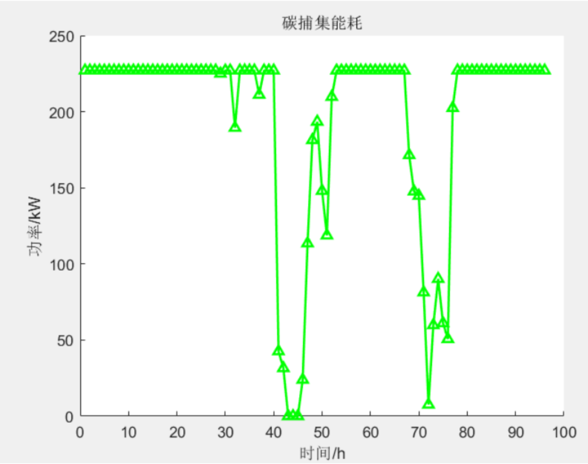
This program implements a virtual power plant/microgrid based on the above literature model.Time ScaleThe low-carbon economic dispatch model of the electric-thermal integrated energy system, on the source side, installs a flue gas bypass system and a solution storage device in the carbon capture power plant to form a comprehensive and flexible operation mode of the carbon capture power plant and coordinate with wind power; on the load side, price-based and incentive-based demand response resources with different response speeds are used to overcome the limitations of the comprehensive and flexible operation mode of the carbon capture power plant under multiple time scales, and the low-carbon performance of the system is improved through coordinated optimization of source and load resources. Secondly, a two-stage low-carbon economic dispatch model of day-ahead and intraday coordination of source and load is constructed to optimize the load and distribution plan of the system.
%% 决策变量
% 电力源出力
GT_P = sdpvar(2,24,'full'); % 燃气轮机电出力
P_w = sdpvar(1,24,'full'); % 风电机组出力
P_G = sdpvar(3,24,'full'); % 火电机组出力
EB=sdpvar(2,24,'full'); % 电锅炉出力
% 热力源出力
GT_H = sdpvar(2,24,'full'); % 燃气轮机热出力
EB_H=sdpvar(2,24,'full'); % 电锅炉热出力
% 天然气
P_gas=sdpvar(2,24,'full'); % 天然气需求
% 碳捕集相关
E_G=sdpvar(3,24,'full'); % 碳捕集机组产生的总碳排放
E_total_co2=sdpvar(3,24,'full'); % 机组捕获的总碳排放
E_CG=sdpvar(3,24,'full'); % 储液装置提供的待捕集二氧化碳量
P_B=sdpvar(3,24,'full'); % 机组运行能耗
P_J=sdpvar(3,24,'full'); % 机组净出力
V_CA=sdpvar(3,24,'full'); % 机组净出力
V_FY=sdpvar(3,24,'full'); % 富液体积
V_PY=sdpvar(3,24,'full'); % 贫液体积
P_tran=sdpvar(1,24,'full'); % 系统可转移电负荷
P_cut=sdpvar(1,24,'full'); % 系统可削减电负荷
P_DE=sdpvar(1,24,'full'); % 系统经过过需求响应后的电负荷
H_tran=sdpvar(1,24,'full'); % 系统可转移热负荷
H_cut=sdpvar(1,24,'full'); % 系统可削减热负荷
H_DE=sdpvar(1,24,'full'); % 系统经过过需求响应后的热负荷
gn=5;
P_G_line= sdpvar(3,24,'full'); % 火电机组出力
%% 约束条件
C = [];  %约束条件初始
for t=1:24
    for i=1:3
    C = [C,
        0<=E_CG(i,t),
        0<=P_B(i,t),
        E_G(i,t)==eg(i)*P_G(i,t), % 碳捕集机组产生的总碳排放
        E_total_co2(i,t)==E_CG(i,t)+0.25*E_bata*eg(i)*(y1(i,t)-y2(i,t)), % 机组捕获的二氧化碳总量
        0<=E_total_co2(i,t)<=P_yita*E_bata*eg(i)*P_G_max(i),
        P_B(i,t)==P_lamda(i)*E_total_co2(i,t), % 机组运行能耗
        P_G(i,t)==P_J(i,t)+P_D(i,t)+P_B(i,t), % 机组输出总功率
        P_G_min(i)-P_lamda(i)*P_yita*E_bata*eg(i)*P_G_max(i)-P_D(i)<=P_J(i,t)<=P_G_max(i)-P_D(i), % 碳捕集电厂净出力范围
        0<= P_w(t)<= P_prew(t), % 风电出力区间约束
        sum(EB(:,t))+P_w(t)<=P_prew(t);
        P_G_min(i)<= P_G(i,t)<=P_G_max(i), % 火电机组出力约束
        ];
    end
end
C=[C,min(sum(R_u),sum(P_G_max)-sum(P_G))>=0.01*max(P_DE),]; % 旋转备用约束


I have devoted myself to the research of technology for more than 30 years. I am proficient in various languages such as Java, Linux, JavaScript, PHP, CSS, etc. I have made many contributions in the field of open source. I have established a developer documentation site to share some problems in technology development for everyone to read.
