
le mie informazioni di contatto
Posta[email protected]
2024-07-12
한어Русский языкEnglishFrançaisIndonesianSanskrit日本語DeutschPortuguêsΕλληνικάespañolItalianoSuomalainenLatina
Sommario
1.1 Informazioni sull'ambiente software e hardware
1.2 Informazioni sulla scheda di sviluppo
2.1 Circuito di interfaccia hardware
2.2 FSB configura l'IO di DS18B20
2.3 Genera file di progetto Keil
3.2 Implementazione del driver DS18B20
3.2.1 Definizione dello stato IO
4.1 Progettazione dell'applicazione
Renesas R7FA8D1BH (Cortex®-M85) controlla DS18B20 e ADC per ottenere la funzione di salto di due pagine
Questo articolo introduce principalmente un caso applicativo completo progettato per Renesas R7FA8D1BH (Cortex®-M85): applicazione dell'IO di R7FA8D1BH per implementare un singolo protocollo bus e realizzazione della funzione di pilotaggio ds18b20 Completa principalmente la lettura del valore della temperatura e la formattazione del valore visualizzazione sull'OLED sullo schermo. I dati sulla temperatura vengono inviati anche al terminale della porta seriale tramite il terminale della porta seriale.
| Informazioni su software e hardware | Informazioni sulla versione |
|---|---|
| MCU di Renesas | Riferimenti |
| Chiglia | Braccio MDK 5.38 |
| Versione FSP | 5.3.0 |
| Strumento di debug: N32G45XVL-STB | Collegamento DAP |
L'autore ha scelto di utilizzare la scheda di sviluppo Wildfire Yaoyang_Renesas RA8. L'MCU di controllo principale di questa scheda è R7FA8D1BHECBD e il nucleo di 7FA8D1BHECBD è ARM Contex-M85.
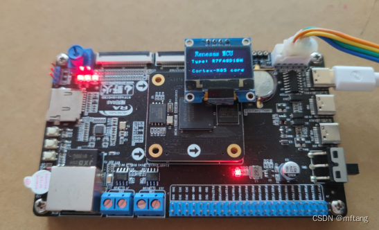
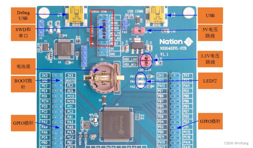
Per il chip R7FA8D1BHECBD, il core utilizzato è Cortex®-M85 Core, ST-LINK-V2 o J-LINK-V9 non supporta le funzioni di download e debug.Dopo molti tentativi, l'autore lo ha scopertoN32G45XVL-STBIl DAP-LINK fornito con la scheda può scaricare ed eseguire il debug di R7FA8D1BHECBD.
L'immagine seguente è un'immagine fisica della scheda di sviluppo N32G45XVL-STB:
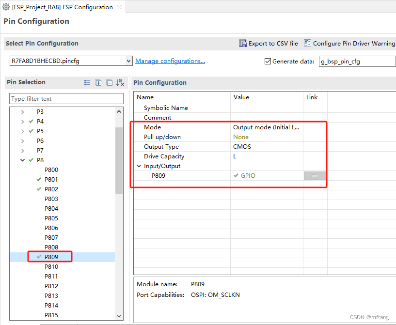
Il circuito di interfaccia del DS18B20 è stato progettato sulla Yaoyang Development Board_Renesas RA8, che utilizza l'interfaccia P809 come segnale di controllo DQ del DS18B20.

Configurare P809 come interfaccia IO comune, quindi configurare dinamicamente l'uscita o lo stato di uscita dell'IO nel codice
Dopo aver completato la configurazione dei parametri di FSP, è possibile generare progetto. Apri il file di progetto, la sua struttura è la seguente:

Creare il file ds18b20.c per implementare il codice del driver
L'autore ha già analizzato in dettaglio le tempistiche e la logica di implementazione del DS18B20 nel suo precedente articolo, quindi non lo introdurrò qui.
Nota applicativa DS18B20_Forma d'onda dei dati di lettura ds18b20-Blog CSDN
Riga 14 del codice: Definisci la funzione di ritardo del passo
Riga 15 del codice: Definire la funzione di ritardo del passo ms
Riga 18 del codice: definire il PIN IO di DS18B20
Riga 21 del codice: configurazione della porta di ingresso
Riga 22 del codice: configurazione della porta di uscita
Riga 24 del codice: imposta il livello IO basso
Riga 25 del codice: imposta il livello IO alto

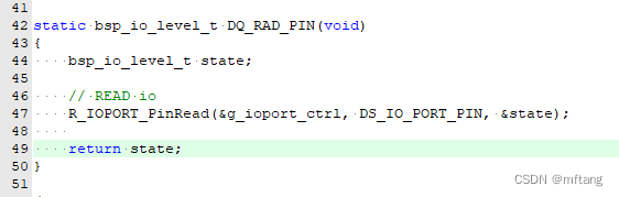
Riga 47 del codice: leggere lo stato di IO in modalità input
Funzione: ds18b20Init, rileva se DS18B20 è online
Funzione: ds18b20BlockModeProcess. Leggi il valore di DS18B20
- /**
- * @brief reset DS18B20
- * @note if reset ds18b20 sucess, the return value is TRUE
- * @param None
- * @retval True or Flalse
- */
- static uint8_t ds18b20Init( void )
- {
- uint16_t tempCnt = 0;
- bsp_io_level_t status;
-
- // Set PIN mode output
- DS_Mode_Out_PP();
-
- // Master pin is high
- DQ_SET_HIGH;
- timeDelayUS(10);
-
- // Master pin is low
- DQ_SET_LOW;
- // wait for 600 us
- timeDelayUS(750);
-
- // Set PIN mode input
- DS_Mode_IN_PUT();
-
- while(1)
- {
- status = DQ_RAD_PIN();
- if( status == 0)
- {
- tempCnt = 0;
- return TRUE;
- }
- else
- {
- timeDelayUS(1);
- tempCnt++;
- if( tempCnt > 480 )
- return FALSE;
- }
- }
- }
-
-
- static uint8_t readBit( void )
- {
- uint8_t readCnt = 2;
- uint8_t bitVal = 1;
-
- DQ_SET_LOW;
- timeDelayUS(3);
- DQ_SET_HIGH;
-
- timeDelayUS(5); // 15 us
-
- while(readCnt-- )
- {
- //read DQ value
- if( DQ_RAD_PIN() == 0)
- {
- bitVal = 0;
- }
- timeDelayUS(2); // 15 us
- }
-
- timeDelayUS(30); // 15 us
-
- return bitVal;
- }
-
- static uint8_t ds18b20ReadByte( void )
- {
- uint8_t byteVal = 0;
-
- for ( uint8_t i = 0; i < 8; i++ )
- {
- byteVal >>= 1;
-
- uint8_t bitVal = readBit();
- if( bitVal > 0)
- {
- byteVal |= 0x80;
- }
- }
-
- return byteVal;
- }
-
-
- /**
- * @brief write one byte to DS18B20
- * @note
- * @param byte: the data that is sended to ds18b20
- * @retval None
- */
- void ds18b20WriteByte( uint8_t byte)
- {
- unsigned char k;
-
- // Set PIN mode output
- DS_Mode_Out_PP();
-
- for ( k = 0; k < 8; k++ )
- {
- if (byte & (1<<k))
- {
- DQ_SET_LOW;
- timeDelayUS(2);
-
- DQ_SET_HIGH;
- timeDelayUS(65);
- }
- else
- {
- DQ_SET_LOW;
- timeDelayUS(65);
-
- DQ_SET_HIGH;
- timeDelayUS(2);
- }
- }
- }
-
- uint8_t ds18b20BlockModeProcess( void )
- {
- uint16_t tempValue;
- uint8_t tempL, tempH;
-
- if (ds18b20Init() == FALSE)
- {
- return FALSE;
- }
-
- // wait for 600 us
- timeDelayUS(600);
-
- ds18b20WriteByte(0xcc);
- ds18b20WriteByte(0x44); // start convert temperature
-
- if (ds18b20Init() == FALSE)
- {
- return FALSE;
- }
- // wait for 600 us
- timeDelayUS(600);
-
- ds18b20WriteByte(0xcc);
- ds18b20WriteByte(0xbe); // read temperature data register
-
- tempL = ds18b20ReadByte();
- tempH = ds18b20ReadByte();
-
- if (tempH > 0x7f)
- {
- tempL = ~tempL;
- tempH = ~tempH+1;
- st_ds1b20val.sign = 1;
- }
-
- tempValue = (uint16_t)((tempH << 8) | tempL);
-
- st_ds1b20val.temperatureVal = (float)(tempValue * 0.0625);
-
- return TRUE;
- }
-
-
- // NO blocking mode operate ds18b20
- uint8_t ds18b20NoBlockingProcess( void )
- {
- uint16_t tempValue;
- static uint16_t waitCnt = 0;
- uint8_t tempL, tempH;
- static uint8_t runState = 0;
-
- switch( runState )
- {
- default:
- case INIT_DQ:
- if (ds18b20Init() == FALSE)
- {
- return FALSE;
- }
- runState = WAIT_READY;
- break;
-
- case WAIT_READY:
- timeDelayUS(2); // IDEL
- runState = SKIDROM_CMD;
- break;
-
- case SKIDROM_CMD:
- ds18b20WriteByte(0xcc);
- ds18b20WriteByte(0x44); // begin to convert temperature data
- waitCnt = 0;
- runState = WAIT_CONVERT;
- break;
-
- case WAIT_CONVERT:
- waitCnt++;
- if( waitCnt > WAIT_CNT_CONVERT)
- {
- waitCnt = 0;
- runState = RESET_CMD;
- }
- break;
-
- case RESET_CMD:
- if (ds18b20Init() == FALSE)
- {
- return FALSE;
- }
- runState = WAIT_DATA_READY;
- break;
-
- case WAIT_DATA_READY:
- timeDelayUS(2); // IDEL
- runState = READ_CMD;
- break;
-
- case READ_CMD:
- ds18b20WriteByte(0xcc);
- ds18b20WriteByte(0xbe); // read temperature data register
- runState = GET_VALUE;
- break;
-
- case GET_VALUE:
-
- tempL = ds18b20ReadByte();
- tempH = ds18b20ReadByte();
-
- if (tempH > 0x7f)
- {
- tempL = ~tempL;
- tempH = ~tempH+1;
- st_ds1b20val.sign = 1;
- }
-
- tempValue = (uint16_t)((tempH << 8) | tempL);
-
- st_ds1b20val.temperatureVal = (float)(tempValue * 0.0625);
- runState = INIT_DQ;
- return TRUE;
- }
-
- return FALSE;
- }
Riga 113 del codice: leggi il valore di ds18b20
Riga 130 del codice: ottieni i dati dei risultati di ds18b20
Riga 131 del codice: dati di visualizzazione formattati
Riga 132 del codice: Visualizza i dati su OLED
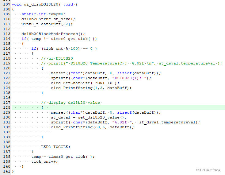
Compila il codice e scarica il codice sulla scheda. I risultati in esecuzione sono i seguenti:

Codice autista DS18B20
1) Crea il file ds18b20.c e scrivi il seguente codice
- /*
- FILE NAME : ds18b20.c
- Description: user ds18b20 interface
- Author : [email protected]
- Date : 2024/06/03
- */
- #include "ds18b20.h"
- #include "hal_data.h"
-
- typedef enum{
- INPUT = 0,
- OUTPUT = 1,
- }IO_TYPE;
-
- typedef enum{
- FALSE = 0,
- TRUE = 1,
- }RETURN_RESULT;
-
- typedef enum{
- INIT_DQ = 0,
- WAIT_READY,
- SKIDROM_CMD,
-
- WAIT_CONVERT,
- RESET_CMD,
- READ_CMD,
-
- WAIT_DATA_READY,
- GET_VALUE,
- IDLE_NULL
- }RUN_STATE;
-
- ds18b20Struc st_ds1b20val;
-
-
- ds18b20Struc get_ds18b20_value( void )
- {
- return st_ds1b20val;
- }
-
- static bsp_io_level_t DQ_RAD_PIN(void)
- {
- bsp_io_level_t state;
-
- // READ io
- R_IOPORT_PinRead(&g_ioport_ctrl, DS_IO_PORT_PIN, &state);
-
- return state;
- }
-
- /**
- * @brief reset DS18B20
- * @note if reset ds18b20 sucess, the return value is TRUE
- * @param None
- * @retval True or Flalse
- */
- static uint8_t ds18b20Init( void )
- {
- uint16_t tempCnt = 0;
- bsp_io_level_t status;
-
- // Set PIN mode output
- DS_Mode_Out_PP();
-
- // Master pin is high
- DQ_SET_HIGH;
- timeDelayUS(10);
-
- // Master pin is low
- DQ_SET_LOW;
- // wait for 600 us
- timeDelayUS(750);
-
- // Set PIN mode input
- DS_Mode_IN_PUT();
-
- while(1)
- {
- status = DQ_RAD_PIN();
- if( status == 0)
- {
- tempCnt = 0;
- return TRUE;
- }
- else
- {
- timeDelayUS(1);
- tempCnt++;
- if( tempCnt > 480 )
- return FALSE;
- }
- }
- }
-
-
- static uint8_t readBit( void )
- {
- uint8_t readCnt = 2;
- uint8_t bitVal = 1;
-
- DQ_SET_LOW;
- timeDelayUS(3);
- DQ_SET_HIGH;
-
- timeDelayUS(5); // 15 us
-
- while(readCnt-- )
- {
- //read DQ value
- if( DQ_RAD_PIN() == 0)
- {
- bitVal = 0;
- }
- timeDelayUS(2); // 15 us
- }
-
- timeDelayUS(30); // 15 us
-
- return bitVal;
- }
-
- static uint8_t ds18b20ReadByte( void )
- {
- uint8_t byteVal = 0;
-
- for ( uint8_t i = 0; i < 8; i++ )
- {
- byteVal >>= 1;
-
- uint8_t bitVal = readBit();
- if( bitVal > 0)
- {
- byteVal |= 0x80;
- }
- }
-
- return byteVal;
- }
-
-
- /**
- * @brief write one byte to DS18B20
- * @note
- * @param byte: the data that is sended to ds18b20
- * @retval None
- */
- void ds18b20WriteByte( uint8_t byte)
- {
- unsigned char k;
-
- // Set PIN mode output
- DS_Mode_Out_PP();
-
- for ( k = 0; k < 8; k++ )
- {
- if (byte & (1<<k))
- {
- DQ_SET_LOW;
- timeDelayUS(2);
-
- DQ_SET_HIGH;
- timeDelayUS(65);
- }
- else
- {
- DQ_SET_LOW;
- timeDelayUS(65);
-
- DQ_SET_HIGH;
- timeDelayUS(2);
- }
- }
- }
-
- uint8_t ds18b20BlockModeProcess( void )
- {
- uint16_t tempValue;
- uint8_t tempL, tempH;
-
- if (ds18b20Init() == FALSE)
- {
- return FALSE;
- }
-
- // wait for 600 us
- timeDelayUS(600);
-
- ds18b20WriteByte(0xcc);
- ds18b20WriteByte(0x44); // start convert temperature
-
- if (ds18b20Init() == FALSE)
- {
- return FALSE;
- }
- // wait for 600 us
- timeDelayUS(600);
-
- ds18b20WriteByte(0xcc);
- ds18b20WriteByte(0xbe); // read temperature data register
-
- tempL = ds18b20ReadByte();
- tempH = ds18b20ReadByte();
-
- if (tempH > 0x7f)
- {
- tempL = ~tempL;
- tempH = ~tempH+1;
- st_ds1b20val.sign = 1;
- }
-
- tempValue = (uint16_t)((tempH << 8) | tempL);
-
- st_ds1b20val.temperatureVal = (float)(tempValue * 0.0625);
-
- return TRUE;
- }
-
-
- // NO blocking mode operate ds18b20
- uint8_t ds18b20NoBlockingProcess( void )
- {
- uint16_t tempValue;
- static uint16_t waitCnt = 0;
- uint8_t tempL, tempH;
- static uint8_t runState = 0;
-
- switch( runState )
- {
- default:
- case INIT_DQ:
- if (ds18b20Init() == FALSE)
- {
- return FALSE;
- }
- runState = WAIT_READY;
- break;
-
- case WAIT_READY:
- timeDelayUS(2); // IDEL
- runState = SKIDROM_CMD;
- break;
-
- case SKIDROM_CMD:
- ds18b20WriteByte(0xcc);
- ds18b20WriteByte(0x44); // begin to convert temperature data
- waitCnt = 0;
- runState = WAIT_CONVERT;
- break;
-
- case WAIT_CONVERT:
- waitCnt++;
- if( waitCnt > WAIT_CNT_CONVERT)
- {
- waitCnt = 0;
- runState = RESET_CMD;
- }
- break;
-
- case RESET_CMD:
- if (ds18b20Init() == FALSE)
- {
- return FALSE;
- }
- runState = WAIT_DATA_READY;
- break;
-
- case WAIT_DATA_READY:
- timeDelayUS(2); // IDEL
- runState = READ_CMD;
- break;
-
- case READ_CMD:
- ds18b20WriteByte(0xcc);
- ds18b20WriteByte(0xbe); // read temperature data register
- runState = GET_VALUE;
- break;
-
- case GET_VALUE:
-
- tempL = ds18b20ReadByte();
- tempH = ds18b20ReadByte();
-
- if (tempH > 0x7f)
- {
- tempL = ~tempL;
- tempH = ~tempH+1;
- st_ds1b20val.sign = 1;
- }
-
- tempValue = (uint16_t)((tempH << 8) | tempL);
-
- st_ds1b20val.temperatureVal = (float)(tempValue * 0.0625);
- runState = INIT_DQ;
- return TRUE;
- }
-
- return FALSE;
- }
-
-
-
- /* End of this file */
2) Crea il file ds18b20.h e scrivi il seguente codice
- /*
- FILE NAME : ds18b20.h
- Description: user ds18b20 interface
- Author : [email protected]
- Date : 2024/06/03
- */
- #ifndef DS18B20_H
- #define DS18B20_H
- #include "hal_data.h"
-
-
- #define WAIT_CNT_CONVERT 500
-
- #define timeDelayUS(us) R_BSP_SoftwareDelay(us, BSP_DELAY_UNITS_MICROSECONDS);
- #define DS_DELAY_MS(ms) R_BSP_SoftwareDelay(ms, BSP_DELAY_UNITS_MILLISECONDS);
-
-
- #define DS_IO_PORT_PIN BSP_IO_PORT_08_PIN_09
-
-
- #define DS_Mode_IN_PUT() R_IOPORT_PinCfg(&g_ioport_ctrl, DS_IO_PORT_PIN, IOPORT_CFG_PORT_DIRECTION_INPUT)
- #define DS_Mode_Out_PP() R_IOPORT_PinCfg(&g_ioport_ctrl, DS_IO_PORT_PIN, IOPORT_CFG_PORT_DIRECTION_OUTPUT)
-
- #define DQ_SET_LOW R_IOPORT_PinWrite(&g_ioport_ctrl, DS_IO_PORT_PIN, BSP_IO_LEVEL_LOW)
- #define DQ_SET_HIGH R_IOPORT_PinWrite(&g_ioport_ctrl, DS_IO_PORT_PIN, BSP_IO_LEVEL_HIGH)
-
-
- typedef struct{
- float temperatureVal;
- bool sign;
- }ds18b20Struc;
-
- uint8_t ds18b20BlockModeProcess( void );
- ds18b20Struc get_ds18b20_value( void );
-
-
- #endif /* DS18B20_H */
-
-

Si dedica alla ricerca tecnologica da più di 30 anni ed è esperto in vari linguaggi come Java, Linux, Javascript, php, css, ecc. Ha dato numerosi contributi nel campo dell'open source stazione di documentazione per gli sviluppatori per condividere alcuni problemi nello sviluppo della tecnologia per riferimento futuro

Posta[email protected]