
minhas informações de contato
Correspondência[email protected]
2024-07-12
한어Русский языкEnglishFrançaisIndonesianSanskrit日本語DeutschPortuguêsΕλληνικάespañolItalianoSuomalainenLatina
Índice
1.1 Informações sobre o ambiente de software e hardware
1.2 Informações do conselho de desenvolvimento
2.1 Circuito de interface de hardware
2.2 FSB configura o IO do DS18B20
2.3 Gerar arquivos de projeto Keil
3.2 Implementação do driver DS18B20
3.2.1 Definição de status de E/S
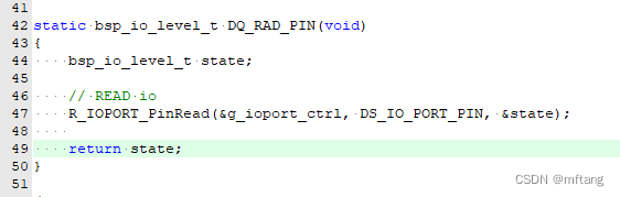
3.2.2 Função de leitura de status IO
Renesas R7FA8D1BH (Cortex®-M85) controla DS18B20 e ADC para alcançar a função de salto de duas páginas
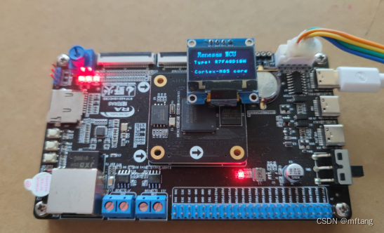
Este artigo apresenta principalmente um caso de aplicação abrangente projetado para Renesas R7FA8D1BH (Cortex®-M85): aplicando o IO de R7FA8D1BH para implementar um protocolo de barramento único e realizando a função de acionar ds18b20. exibir em OLED na tela. Os dados de temperatura também são enviados para o terminal da porta serial através do terminal da porta serial.
| Informações de software e hardware | Versão informação |
|---|---|
| Renesas MCU | R7FA8D1BH |
| Queda | MDK ARM 5.38 |
| Versão FSP | 5.3.0 |
| Ferramenta de depuração: N32G45XVL-STB | Link DAP |
O autor optou por usar a placa de desenvolvimento Wildfire Yaoyang_Renesas RA8. O MCU de controle principal desta placa é R7FA8D1BHECBD, e o núcleo de 7FA8D1BHECBD é ARM Contex-M85.
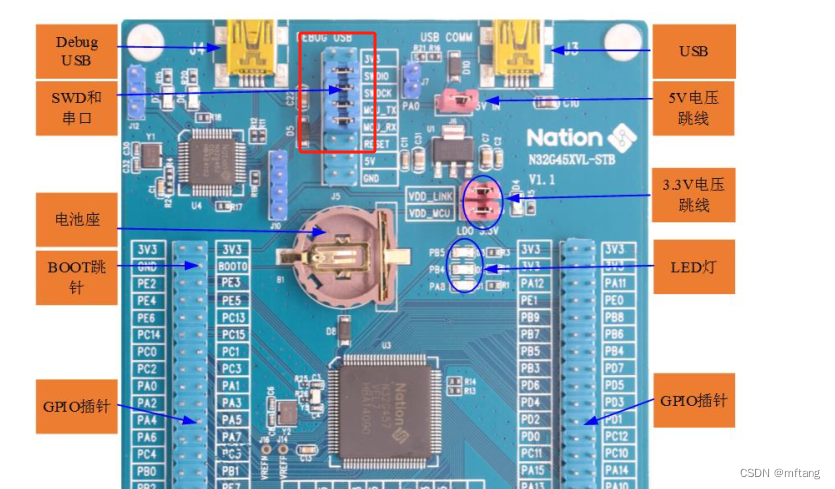
Para o chip R7FA8D1BHECBD, o núcleo usado é Cortex®-M85 Core, ST-LINK-V2 ou J-LINK-V9 não suporta funções de download e depuração.Depois de muitas tentativas, o autor descobriu queN32G45XVL-STBO DAP-LINK que acompanha a placa pode baixar e depurar R7FA8D1BHECBD.
A imagem abaixo é uma imagem física da placa de desenvolvimento N32G45XVL-STB:
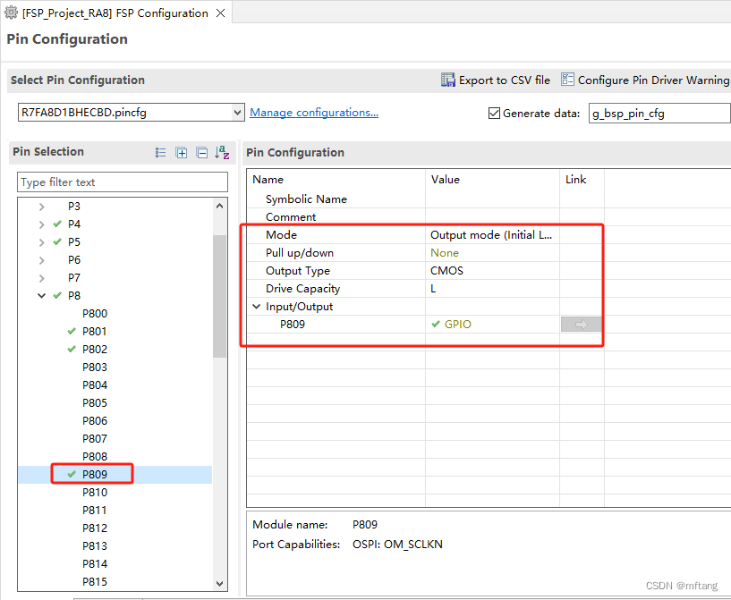
O circuito de interface do DS18B20 foi projetado na placa de desenvolvimento Yaoyang_Renesas RA8, que usa a interface P809 como sinal de controle DQ do DS18B20.

Configure P809 como uma interface IO comum e, em seguida, configure dinamicamente a saída ou status de saída do IO no código
Após concluir a configuração dos parâmetros do FSP, você pode Gerar Projeto. Abra o arquivo do projeto, sua estrutura é a seguinte:

Crie o arquivo ds18b20.c para implementar o código do driver
No artigo anterior, o autor analisou detalhadamente o tempo e a lógica de implementação do DS18B20, portanto não irei apresentá-lo aqui.
DS18B20 Application Note_Waveform de ds18b20 lendo dados-Blog CSDN
Linha 14 do código: Defina a função de atraso de passo
Linha 15 do código: Definir função de atraso de passo ms
Linha 18 do código: Defina o PIN IO do DS18B20
Linha 21 do código: Configuração da porta de entrada
Linha 22 do código: Configuração da porta de saída
Linha 24 do código: Definir nível baixo de IO
Linha 25 do código: Definir IO de alto nível

Linha 47 do código: Leia o status do IO no modo de entrada
Função: ds18b20Init, detecta se DS18B20 está online
Função: ds18b20BlockModeProcess. Leia o valor de DS18B20
- /**
- * @brief reset DS18B20
- * @note if reset ds18b20 sucess, the return value is TRUE
- * @param None
- * @retval True or Flalse
- */
- static uint8_t ds18b20Init( void )
- {
- uint16_t tempCnt = 0;
- bsp_io_level_t status;
-
- // Set PIN mode output
- DS_Mode_Out_PP();
-
- // Master pin is high
- DQ_SET_HIGH;
- timeDelayUS(10);
-
- // Master pin is low
- DQ_SET_LOW;
- // wait for 600 us
- timeDelayUS(750);
-
- // Set PIN mode input
- DS_Mode_IN_PUT();
-
- while(1)
- {
- status = DQ_RAD_PIN();
- if( status == 0)
- {
- tempCnt = 0;
- return TRUE;
- }
- else
- {
- timeDelayUS(1);
- tempCnt++;
- if( tempCnt > 480 )
- return FALSE;
- }
- }
- }
-
-
- static uint8_t readBit( void )
- {
- uint8_t readCnt = 2;
- uint8_t bitVal = 1;
-
- DQ_SET_LOW;
- timeDelayUS(3);
- DQ_SET_HIGH;
-
- timeDelayUS(5); // 15 us
-
- while(readCnt-- )
- {
- //read DQ value
- if( DQ_RAD_PIN() == 0)
- {
- bitVal = 0;
- }
- timeDelayUS(2); // 15 us
- }
-
- timeDelayUS(30); // 15 us
-
- return bitVal;
- }
-
- static uint8_t ds18b20ReadByte( void )
- {
- uint8_t byteVal = 0;
-
- for ( uint8_t i = 0; i < 8; i++ )
- {
- byteVal >>= 1;
-
- uint8_t bitVal = readBit();
- if( bitVal > 0)
- {
- byteVal |= 0x80;
- }
- }
-
- return byteVal;
- }
-
-
- /**
- * @brief write one byte to DS18B20
- * @note
- * @param byte: the data that is sended to ds18b20
- * @retval None
- */
- void ds18b20WriteByte( uint8_t byte)
- {
- unsigned char k;
-
- // Set PIN mode output
- DS_Mode_Out_PP();
-
- for ( k = 0; k < 8; k++ )
- {
- if (byte & (1<<k))
- {
- DQ_SET_LOW;
- timeDelayUS(2);
-
- DQ_SET_HIGH;
- timeDelayUS(65);
- }
- else
- {
- DQ_SET_LOW;
- timeDelayUS(65);
-
- DQ_SET_HIGH;
- timeDelayUS(2);
- }
- }
- }
-
- uint8_t ds18b20BlockModeProcess( void )
- {
- uint16_t tempValue;
- uint8_t tempL, tempH;
-
- if (ds18b20Init() == FALSE)
- {
- return FALSE;
- }
-
- // wait for 600 us
- timeDelayUS(600);
-
- ds18b20WriteByte(0xcc);
- ds18b20WriteByte(0x44); // start convert temperature
-
- if (ds18b20Init() == FALSE)
- {
- return FALSE;
- }
- // wait for 600 us
- timeDelayUS(600);
-
- ds18b20WriteByte(0xcc);
- ds18b20WriteByte(0xbe); // read temperature data register
-
- tempL = ds18b20ReadByte();
- tempH = ds18b20ReadByte();
-
- if (tempH > 0x7f)
- {
- tempL = ~tempL;
- tempH = ~tempH+1;
- st_ds1b20val.sign = 1;
- }
-
- tempValue = (uint16_t)((tempH << 8) | tempL);
-
- st_ds1b20val.temperatureVal = (float)(tempValue * 0.0625);
-
- return TRUE;
- }
-
-
- // NO blocking mode operate ds18b20
- uint8_t ds18b20NoBlockingProcess( void )
- {
- uint16_t tempValue;
- static uint16_t waitCnt = 0;
- uint8_t tempL, tempH;
- static uint8_t runState = 0;
-
- switch( runState )
- {
- default:
- case INIT_DQ:
- if (ds18b20Init() == FALSE)
- {
- return FALSE;
- }
- runState = WAIT_READY;
- break;
-
- case WAIT_READY:
- timeDelayUS(2); // IDEL
- runState = SKIDROM_CMD;
- break;
-
- case SKIDROM_CMD:
- ds18b20WriteByte(0xcc);
- ds18b20WriteByte(0x44); // begin to convert temperature data
- waitCnt = 0;
- runState = WAIT_CONVERT;
- break;
-
- case WAIT_CONVERT:
- waitCnt++;
- if( waitCnt > WAIT_CNT_CONVERT)
- {
- waitCnt = 0;
- runState = RESET_CMD;
- }
- break;
-
- case RESET_CMD:
- if (ds18b20Init() == FALSE)
- {
- return FALSE;
- }
- runState = WAIT_DATA_READY;
- break;
-
- case WAIT_DATA_READY:
- timeDelayUS(2); // IDEL
- runState = READ_CMD;
- break;
-
- case READ_CMD:
- ds18b20WriteByte(0xcc);
- ds18b20WriteByte(0xbe); // read temperature data register
- runState = GET_VALUE;
- break;
-
- case GET_VALUE:
-
- tempL = ds18b20ReadByte();
- tempH = ds18b20ReadByte();
-
- if (tempH > 0x7f)
- {
- tempL = ~tempL;
- tempH = ~tempH+1;
- st_ds1b20val.sign = 1;
- }
-
- tempValue = (uint16_t)((tempH << 8) | tempL);
-
- st_ds1b20val.temperatureVal = (float)(tempValue * 0.0625);
- runState = INIT_DQ;
- return TRUE;
- }
-
- return FALSE;
- }
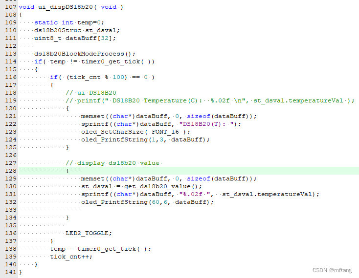
Linha 113 do código: Leia o valor de ds18b20
Linha 130 do código: Obtenha os dados do resultado de ds18b20
Linha 131 do código: Dados de exibição formatados
Linha 132 do código: Exibir dados em OLED
Compile o código e baixe-o para a placa. Os resultados da execução são os seguintes:

Código do driver DS18B20
1) Crie o arquivo ds18b20.c e escreva o seguinte código
- /*
- FILE NAME : ds18b20.c
- Description: user ds18b20 interface
- Author : [email protected]
- Date : 2024/06/03
- */
- #include "ds18b20.h"
- #include "hal_data.h"
-
- typedef enum{
- INPUT = 0,
- OUTPUT = 1,
- }IO_TYPE;
-
- typedef enum{
- FALSE = 0,
- TRUE = 1,
- }RETURN_RESULT;
-
- typedef enum{
- INIT_DQ = 0,
- WAIT_READY,
- SKIDROM_CMD,
-
- WAIT_CONVERT,
- RESET_CMD,
- READ_CMD,
-
- WAIT_DATA_READY,
- GET_VALUE,
- IDLE_NULL
- }RUN_STATE;
-
- ds18b20Struc st_ds1b20val;
-
-
- ds18b20Struc get_ds18b20_value( void )
- {
- return st_ds1b20val;
- }
-
- static bsp_io_level_t DQ_RAD_PIN(void)
- {
- bsp_io_level_t state;
-
- // READ io
- R_IOPORT_PinRead(&g_ioport_ctrl, DS_IO_PORT_PIN, &state);
-
- return state;
- }
-
- /**
- * @brief reset DS18B20
- * @note if reset ds18b20 sucess, the return value is TRUE
- * @param None
- * @retval True or Flalse
- */
- static uint8_t ds18b20Init( void )
- {
- uint16_t tempCnt = 0;
- bsp_io_level_t status;
-
- // Set PIN mode output
- DS_Mode_Out_PP();
-
- // Master pin is high
- DQ_SET_HIGH;
- timeDelayUS(10);
-
- // Master pin is low
- DQ_SET_LOW;
- // wait for 600 us
- timeDelayUS(750);
-
- // Set PIN mode input
- DS_Mode_IN_PUT();
-
- while(1)
- {
- status = DQ_RAD_PIN();
- if( status == 0)
- {
- tempCnt = 0;
- return TRUE;
- }
- else
- {
- timeDelayUS(1);
- tempCnt++;
- if( tempCnt > 480 )
- return FALSE;
- }
- }
- }
-
-
- static uint8_t readBit( void )
- {
- uint8_t readCnt = 2;
- uint8_t bitVal = 1;
-
- DQ_SET_LOW;
- timeDelayUS(3);
- DQ_SET_HIGH;
-
- timeDelayUS(5); // 15 us
-
- while(readCnt-- )
- {
- //read DQ value
- if( DQ_RAD_PIN() == 0)
- {
- bitVal = 0;
- }
- timeDelayUS(2); // 15 us
- }
-
- timeDelayUS(30); // 15 us
-
- return bitVal;
- }
-
- static uint8_t ds18b20ReadByte( void )
- {
- uint8_t byteVal = 0;
-
- for ( uint8_t i = 0; i < 8; i++ )
- {
- byteVal >>= 1;
-
- uint8_t bitVal = readBit();
- if( bitVal > 0)
- {
- byteVal |= 0x80;
- }
- }
-
- return byteVal;
- }
-
-
- /**
- * @brief write one byte to DS18B20
- * @note
- * @param byte: the data that is sended to ds18b20
- * @retval None
- */
- void ds18b20WriteByte( uint8_t byte)
- {
- unsigned char k;
-
- // Set PIN mode output
- DS_Mode_Out_PP();
-
- for ( k = 0; k < 8; k++ )
- {
- if (byte & (1<<k))
- {
- DQ_SET_LOW;
- timeDelayUS(2);
-
- DQ_SET_HIGH;
- timeDelayUS(65);
- }
- else
- {
- DQ_SET_LOW;
- timeDelayUS(65);
-
- DQ_SET_HIGH;
- timeDelayUS(2);
- }
- }
- }
-
- uint8_t ds18b20BlockModeProcess( void )
- {
- uint16_t tempValue;
- uint8_t tempL, tempH;
-
- if (ds18b20Init() == FALSE)
- {
- return FALSE;
- }
-
- // wait for 600 us
- timeDelayUS(600);
-
- ds18b20WriteByte(0xcc);
- ds18b20WriteByte(0x44); // start convert temperature
-
- if (ds18b20Init() == FALSE)
- {
- return FALSE;
- }
- // wait for 600 us
- timeDelayUS(600);
-
- ds18b20WriteByte(0xcc);
- ds18b20WriteByte(0xbe); // read temperature data register
-
- tempL = ds18b20ReadByte();
- tempH = ds18b20ReadByte();
-
- if (tempH > 0x7f)
- {
- tempL = ~tempL;
- tempH = ~tempH+1;
- st_ds1b20val.sign = 1;
- }
-
- tempValue = (uint16_t)((tempH << 8) | tempL);
-
- st_ds1b20val.temperatureVal = (float)(tempValue * 0.0625);
-
- return TRUE;
- }
-
-
- // NO blocking mode operate ds18b20
- uint8_t ds18b20NoBlockingProcess( void )
- {
- uint16_t tempValue;
- static uint16_t waitCnt = 0;
- uint8_t tempL, tempH;
- static uint8_t runState = 0;
-
- switch( runState )
- {
- default:
- case INIT_DQ:
- if (ds18b20Init() == FALSE)
- {
- return FALSE;
- }
- runState = WAIT_READY;
- break;
-
- case WAIT_READY:
- timeDelayUS(2); // IDEL
- runState = SKIDROM_CMD;
- break;
-
- case SKIDROM_CMD:
- ds18b20WriteByte(0xcc);
- ds18b20WriteByte(0x44); // begin to convert temperature data
- waitCnt = 0;
- runState = WAIT_CONVERT;
- break;
-
- case WAIT_CONVERT:
- waitCnt++;
- if( waitCnt > WAIT_CNT_CONVERT)
- {
- waitCnt = 0;
- runState = RESET_CMD;
- }
- break;
-
- case RESET_CMD:
- if (ds18b20Init() == FALSE)
- {
- return FALSE;
- }
- runState = WAIT_DATA_READY;
- break;
-
- case WAIT_DATA_READY:
- timeDelayUS(2); // IDEL
- runState = READ_CMD;
- break;
-
- case READ_CMD:
- ds18b20WriteByte(0xcc);
- ds18b20WriteByte(0xbe); // read temperature data register
- runState = GET_VALUE;
- break;
-
- case GET_VALUE:
-
- tempL = ds18b20ReadByte();
- tempH = ds18b20ReadByte();
-
- if (tempH > 0x7f)
- {
- tempL = ~tempL;
- tempH = ~tempH+1;
- st_ds1b20val.sign = 1;
- }
-
- tempValue = (uint16_t)((tempH << 8) | tempL);
-
- st_ds1b20val.temperatureVal = (float)(tempValue * 0.0625);
- runState = INIT_DQ;
- return TRUE;
- }
-
- return FALSE;
- }
-
-
-
- /* End of this file */
2) Crie o arquivo ds18b20.h e escreva o seguinte código
- /*
- FILE NAME : ds18b20.h
- Description: user ds18b20 interface
- Author : [email protected]
- Date : 2024/06/03
- */
- #ifndef DS18B20_H
- #define DS18B20_H
- #include "hal_data.h"
-
-
- #define WAIT_CNT_CONVERT 500
-
- #define timeDelayUS(us) R_BSP_SoftwareDelay(us, BSP_DELAY_UNITS_MICROSECONDS);
- #define DS_DELAY_MS(ms) R_BSP_SoftwareDelay(ms, BSP_DELAY_UNITS_MILLISECONDS);
-
-
- #define DS_IO_PORT_PIN BSP_IO_PORT_08_PIN_09
-
-
- #define DS_Mode_IN_PUT() R_IOPORT_PinCfg(&g_ioport_ctrl, DS_IO_PORT_PIN, IOPORT_CFG_PORT_DIRECTION_INPUT)
- #define DS_Mode_Out_PP() R_IOPORT_PinCfg(&g_ioport_ctrl, DS_IO_PORT_PIN, IOPORT_CFG_PORT_DIRECTION_OUTPUT)
-
- #define DQ_SET_LOW R_IOPORT_PinWrite(&g_ioport_ctrl, DS_IO_PORT_PIN, BSP_IO_LEVEL_LOW)
- #define DQ_SET_HIGH R_IOPORT_PinWrite(&g_ioport_ctrl, DS_IO_PORT_PIN, BSP_IO_LEVEL_HIGH)
-
-
- typedef struct{
- float temperatureVal;
- bool sign;
- }ds18b20Struc;
-
- uint8_t ds18b20BlockModeProcess( void );
- ds18b20Struc get_ds18b20_value( void );
-
-
- #endif /* DS18B20_H */
-
-

Ele se dedica à pesquisa de tecnologia há mais de 30 anos e é proficiente em diversas linguagens como java, linux, javascript, php, css, etc. estação de documentação do desenvolvedor para compartilhar alguns problemas no desenvolvimento de tecnologia para referência futura.

Correspondência[email protected]