2024-07-12
한어Русский языкEnglishFrançaisIndonesianSanskrit日本語DeutschPortuguêsΕλληνικάespañolItalianoSuomalainenLatina
NAT Address Translation
DR Direct Routing Mode
tun tunnel mode
The scheduler is the most important in the entire LVS cluster. In NAT mode, the load receives requests, forwards traffic according to the load balancing algorithm, and sends responses to the client.
DR mode: The scheduler is still responsible for receiving requests and forwarding them to the RS according to the load balancing algorithm. The RS responds directly to the client.
Direct Routing is a二层转发模式The second layer forwarding is数据帧.according to源mac地址和目的mac地址Forward.
The source IP and destination IP of the data packet will not be modified, and it will be forwarded according to the MAC address of the data packet.
In DR mode, LVS also maintains a virtual IP address, and all requests are sent to this VIP. Since it is a Layer 2 forwarding, when the client's request reaches the scheduler, an RS is selected according to the load balancing algorithm, and the destination MAC of the VIP server is modified to the MAC address of the RS. After the RS completes the request, it directly sends the response to the client based on the source MAC address of the client in the message, without going through the scheduler.
VIP address conflict, scheduler and RS are in the same network segment, ARP communication disorder. Because the entire LAN broadcasts, all devices receive it.
How to block the loopback response of lo so that only the physical IP address of the server responds.
arp_ignore=1------#The server system's physical IP address will respond to the request, lo will not respond to ARP requests.
2. When the message is returned, the VIP address is still there. How can the client receive the response?
arp_announce=2—#The system does not use the source address of the IP packet to respond to the request, but directly sends the IP address of the physical interface.
1、调度器的ip地址和RS的ip要在同一网段,数据先进行二层转发。

2、RS是一个公网地址,互联网可以直接访问RS的地址(不用)。

3、DR模式是走内核转发,内核来判断数据包的地址,根据RS的地址把数据包重新封装,修改mac地址。
4、调度器的地址只可以做为集群访问的入口,不能作为网关。

5、所有的RS上的lo(本地回环地址)都要配置vip地址。


nignx1:RS1 192.168.168.10+vip
nginx2: RS2 192.168.168.20+vip
VIP: 192.168.168.100
test1: scheduler vip
test2: client
On the scheduler
vim /etc/sysctl.conf

net.ipv4.ip_forward=0
#关闭数据包转发功能
net.ipv4.conf.all.send_redirects=0
#禁止系统发送icmp重定向的消息。回环地址不接受ping得消息。只针对真实得ip地址。
net.ipv4.conf.default.send_redirects=0
#禁止默认网络接口发送icmp重定向的消息。
net.ipv4.conf.ens33.send_redirects=0
#针对ens33设备,禁止发送icmp重定向消息。
-A Add virtual server vip
-D Delete virtual server address
-s specifies the load balancing scheduling algorithm
-a Add real server
-d delete real server
-t specifies the address and port of vip
-r specifies the address and port of rip
-m use NAT mode
-g Use DR mode
-i Use tunnel mode
-w Set weight
-p 60: Set the connection hold time to 60
-l: List view
-n: Digital display
-m specifies the mode as NAT mode
Set the IP address 192.168.168.100 to the loopback interface as the VIP of LVS. Forward to RS through the routing mode
It allows VIP to identify the real server of RS.
route add -host 192.168.233.100 dev lo:0
vim /etc/sysctl.conf
net.ipv4.conf.lo.arp_ignore = 1
#设置回环接口忽略来自任何接口的ARP请求net.ipv4.conf.lo.arp_announce =2
设置回环地址仅仅公告本地的ip地址,但是不响应ARP请求net.ipv4.conf.all.arp_ignore = 1
#设置所有接口忽略来自任何接口的ARP请求net.ipv4.conf.all.arp_announce =2
#设置所有接口仅仅公告本地的ip地址,但是不响应ARP请求。
3. In Linux system,net.ipv4.conf.all.arp_ignore It is a kernel parameter that controls how the network interface handles received ARP (Address Resolution Protocol) requests. This parameter is especially configured in servers and network devices to reduce security risks caused by ARP spoofing or other network attacks.
When setting net.ipv4.conf.all.arp_ignore = 1 This means that the system will only answer ARP requests whose target IP address is the address on the receiving interface of the local machine. In other words, if the target IP address of the ARP request does not match the IP address on the interface receiving the request, the system will ignore the ARP request. This setting is particularly useful for enhancing the system's resistance to ARP spoofing attacks.
Specifically,arp_ignore The parameter can have multiple values, each representing a different behavior:
0(Default): Respond to any ARP request on any network interface, as long as the request's target IP address matches an IP address on the local machine.1: Only respond to ARP requests where the destination IP address is the receiving interface's IP address. This helps prevent the interface from being used as a proxy for other machines.2: Only responds to ARP requests that match the primary IP address if the destination IP address of the ARP request is the IP address of the receiving interface and that interface is primary (i.e., if an interface is configured with multiple IP addresses, only ARP requests that match the primary IP address will be responded to).4. In Linux system,net.ipv4.conf.all.arp_announce Is a kernel parameter that controls the IP address selection strategy used by a network interface when sending an ARP (Address Resolution Protocol) request or response. This parameter is particularly useful for preventing ARP spoofing and network address conflicts, because it allows the system to more carefully select the source IP address used for ARP communication.
When setting net.ipv4.conf.all.arp_announce = 2 This means that the system will only use the primary IP address of an interface on the same subnet as the requested target IP address when sending ARP requests or responses (if any). If there is no such interface, no ARP request or response is sent. This setting can help reduce network problems caused by ARP spoofing because it limits the interfaces and IP addresses to which ARP traffic can be sent.
arp_announce The parameter can have the following values:
0(Default): Choose any IP address on any interface for ARP requests or responses. This can cause security issues because an attacker might be able to trick the system into using an IP address that should not be used for ARP communication.1: Try to avoid using IP addresses on non-solicited interfaces as the source IP address of ARP requests. However, if there is no other choice, IP addresses on non-solicited interfaces may still be used.2: Use only the primary IP address of an interface that is on the same subnet as the requested target IP address (if any). This is the most restrictive setting and helps prevent ARP spoofing.| NAT | DR | TUN | |
|---|---|---|---|
| advantage | Simple configuration, address translation | Best performance | WAN can realize data packet forwarding over longer distances |
| shortcoming | Performance bottleneck | Does not support cross-segment | Dedicated channel, you need to open a VPN (cost money) |
| RS Requirements | No restrictions | It is necessary to stop ARP responses on non-physical interfaces | To support tunnel mode |
| Number of RS | 10-20 | 100 units | 100 units |
ipvsadm -E -t 192.168.233.100:80 -s wrr
ipvsadm -e -t 192.168.233.100:80 -r 192.168.233.61:80 -w 3
LVS working mode and its working process:
LVS has three load balancing modes: VS/NAT (NAT mode), VS/DR (routing mode), and VS/TUN (tunnel mode).
1. NAT mode (VS-NAT)
Principle: First, when the load balancer receives the client's request data packet, it decides to which backend real server (RS) to send the request based on the scheduling algorithm.
The load balancer then changes the destination IP address and port of the request data packet sent by the client to the IP address (RIP) of the backend real server.
After the real server responds to the request, it checks the default route and sends the response data packet to the load balancer. After receiving the response packet, the load balancer
Change the source address of the packet to the virtual address (VIP) and send it back to the client.
Advantages: The servers in the cluster can use any operating system that supports TCP/IP, as long as the load balancer has a valid IP address.
Disadvantages: Limited scalability. When the number of server nodes increases too much, all requests and responses need to go through the load balancer.
Therefore, the load balancer will become the bottleneck of the entire system.
2. Direct Routing Mode (VS-DR)
Principle: First, when the load balancer receives the client's request data packet, it decides to which backend real server (RS) to send the request based on the scheduling algorithm.
The load balancer then changes the destination MAC address of the request data packet sent by the client to the MAC address of the backend real server (R-MAC).
After the real server responds to the request, it checks the default route and sends the response data packet directly to the client without going through the load balancer.
Advantages: The load balancer is only responsible for distributing request packets to the backend node server, while RS sends the response packet directly to the user.
Therefore, a large amount of data flow to the load balancer is reduced, and the load balancer is no longer the bottleneck of the system and can handle a huge amount of requests.
Disadvantages: The load balancer and the real server RS need to have a network card connected to the same physical network segment and must be in the same LAN environment.
3. IP Tunnel Mode (VS-TUN)
Principle: First, when the load balancer receives the client's request data packet, it decides to which backend real server (RS) to send the request based on the scheduling algorithm.
The load balancer then encapsulates the request message sent by the client into an IP tunnel (T-IP) and forwards it to the real server (RS).
After the real server responds to the request, it checks the default route and sends the response data packet directly to the client without going through the load balancer.
Advantages: The load balancer is only responsible for distributing request packets to the backend node server, while RS sends the response packet directly to the user.
Therefore, a large amount of data flow to the load balancer is reduced, and the load balancer is no longer the bottleneck of the system and can handle a huge amount of requests.
Disadvantages: The RS node in tunnel mode requires a valid IP, and this method requires all servers to support "IP Tunneling".
The high availability architecture in the LVS cluster is only for the high availability of the scheduler.
The master and backup schedulers are implemented based on VRRP.
Highly available HA architecture.
Main scheduler, backup scheduler (multiple)
When the main scheduler is working normally, the backup is in a completely redundant state (on standby). It does not participate in the operation of the cluster. Only when the main scheduler fails, the backup will take over the work of the main scheduler. When the main scheduler resumes function, the main scheduler continues to serve as the entrance to the cluster, and the backup continues to be in a redundant state (depending on the priority).
Keepaliva implements a high-availability solution based on the VRRP protocol.
1. Multicast address:
224.0.0.18 communicates based on the multicast address, and the master and backup send messages to each other to determine whether the other party is alive.
2. Determine the positions of the primary and backup nodes based on their priorities.
3. Failure switching: if the primary server fails, the backup server will continue to work; if the primary server recovers, the backup server will continue to wait.
4. The switch between the primary and backup is the switch of the VIP address.
Keepalive is specifically for LVS, but it is not exclusive to LVS.


LVS is a four-layer forwarding kernel-mode ip+port four-layer proxy
Nginx four-layer proxy can also be a seven-layer proxy
lvs (DR mode) + nginx + tomcat
LVS implements layer 4 forwarding + nginx implements layer 7 forwarding (dynamic)
Accessing the VIP address of lvs can achieve dynamic and static separation.


Implementation of DR mode:
nignx1:RS1 192.168.168.10
nginx2: RS2 192.168.168.20
VIP: 192.168.168.100
test1: scheduler 192.168.168.50
test2: client 192.168.168.60
test1: scheduler
modprobe ip_vs boot kernel
yum -y install ipvsadm* Install lvs management tool
[root@test5 ~]# cd /etc/sysconfig/network-scripts/
[root@test5 network-scripts]# vim ifcfg-ens33:0
DEVICE=ens33:0 ##Add a virtual network card
ONBOOT=yes
IPADDR=192.168.168.100
NETMASK=255.255.255.0
ifup ens33:0
ifconfig

vim /etc/sysctl.conf

net.ipv4.ip_forward=0

#关闭数据包转发功能

net.ipv4.conf.all.send_redirects=0

#禁止系统发送icmp重定向的消息。###lo回环接口不接收icmp消息。只针对真实的ip地址。

net.ipv4.conf.default.send_redirects=0

#禁止网络接口发送icmp重定向的消息。

net.ipv4.conf.ens33.send_redirects=0

#针对ens33设备,禁止发送icmp重定向消息。

sysctl -p
net.ipv4.ip_forward = 0
net.ipv4.conf.all.send_redirects = 0
net.ipv4.conf.default.send_redirects = 0
net.ipv4.conf.ens33.send_redirects = 0
Scheduler starts forwarding
ipvsadm -A -t 192.168.168.100:80 -s rr
[root@test5 opt]# ipvsadm -a -t 192.168.168.100:80 -r 192.168.168.10:80 -g
[root@test5 opt]# ipvsadm -a -t 192.168.168.100:80 -r 192.168.168.20:80 -g
[root@test5 opt]# ipvsadm-save > /etc/sysconfig/ipvsadm
[root@test5 opt]# ipvsadm -ln
IP Virtual Server version 1.2.1 (size=4096)
Prot LocalAddress:Port Scheduler Flags
  -> RemoteAddress:Port           Forward Weight ActiveConn InActConn
TCP  192.168.168.100:80 rr
  -> 192.168.168.10:80            Route   1      0          0
  -> 192.168.168.20:80            Route   1      0          0
Setting up a virtual loopback interface
服务器1:

vim /usr/local/nginx/html/index.html

this is nginx1

systemctl restart nginx

服务器2:

vim /usr/local/nginx/html/index.html

this is nginx2

systemctl restart nginx

同时开启:

DEVICE=lo:0
IPADDR=192.168.168.100
NETMASK=255.255.255.255

ONBOOT=yes
cd /etc/sysconfig/network-scripts/
vim /etc/sysctl.conf
route add -host 192.168.168.100 dev lo:0
Set the IP address of 192.168.168.100 to be added only to the loopback interface as the VIP of LVS. Forwarding to RS through the routing mode allows the VIP to identify the real server.
vim /etc/sysctl.conf
net.ipv4.conf.lo.arp_ignore = 1
#Set the loopback interface to ignore ARP requests from any interface
net.ipv4.conf.lo.arp_announce = 2
#Set the loopback address to only announce the local IP address, but do not respond to ARP requests
net.ipv4.conf.all.arp_ignore = 1
##Set all interfaces to ignore ARP requests from any interface
net.ipv4.conf.all.arp_announce = 2
##Set all interfaces to only announce local IP addresses, but not respond to ARP requests.
sysctl -p
curl 192.168.168.100


Implementation of DR mode:
nignx1:RS1 192.168.168.10
nginx2: RS2 192.168.168.20
VIP: 192.168.168.100
test1: scheduler 192.168.168.50
test2: client 192.168.168.60
test1: scheduler
modprobe ip_vs boot kernel
yum -y install ipvsadm* Install lvs management tool
[root@test5 ~]# cd /etc/sysconfig/network-scripts/
[root@test5 network-scripts]# vim ifcfg-ens33:0
DEVICE=ens33:0 ##Add a virtual network card
ONBOOT=yes
IPADDR=192.168.168.100
NETMASK=255.255.255.0
ifup ens33:0
ifconfig

vim /etc/sysctl.conf

net.ipv4.ip_forward=0

#关闭数据包转发功能

net.ipv4.conf.all.send_redirects=0

#禁止系统发送icmp重定向的消息。###lo回环接口不接收icmp消息。只针对真实的ip地址。

net.ipv4.conf.default.send_redirects=0

#禁止网络接口发送icmp重定向的消息。

net.ipv4.conf.ens33.send_redirects=0

#针对ens33设备,禁止发送icmp重定向消息。

sysctl -p
net.ipv4.ip_forward = 0
net.ipv4.conf.all.send_redirects = 0
net.ipv4.conf.default.send_redirects = 0
net.ipv4.conf.ens33.send_redirects = 0
Scheduler starts forwarding
ipvsadm -A -t 192.168.168.100:80 -s rr
[root@test5 opt]# ipvsadm -a -t 192.168.168.100:80 -r 192.168.168.10:80 -g
[root@test5 opt]# ipvsadm -a -t 192.168.168.100:80 -r 192.168.168.20:80 -g
[root@test5 opt]# ipvsadm-save > /etc/sysconfig/ipvsadm
[root@test5 opt]# ipvsadm -ln
IP Virtual Server version 1.2.1 (size=4096)
Prot LocalAddress:Port Scheduler Flags
  -> RemoteAddress:Port           Forward Weight ActiveConn InActConn
TCP  192.168.168.100:80 rr
  -> 192.168.168.10:80            Route   1      0          0
  -> 192.168.168.20:80            Route   1      0          0
Setting up a virtual loopback interface
服务器1:

vim /usr/local/nginx/html/index.html

this is nginx1

systemctl restart nginx

服务器2:

vim /usr/local/nginx/html/index.html

this is nginx2

systemctl restart nginx

同时开启:

DEVICE=lo:0
IPADDR=192.168.168.100
NETMASK=255.255.255.255

ONBOOT=yes
cd /etc/sysconfig/network-scripts/
vim /etc/sysctl.conf
route add -host 192.168.168.100 dev lo:0
Set the IP address of 192.168.168.100 to be added only to the loopback interface as the VIP of LVS. Forwarding to RS through the routing mode allows the VIP to identify the real server.
vim /etc/sysctl.conf
net.ipv4.conf.lo.arp_ignore = 1
#Set the loopback interface to ignore ARP requests from any interface
net.ipv4.conf.lo.arp_announce = 2
#Set the loopback address to only announce the local IP address, but do not respond to ARP requests
net.ipv4.conf.all.arp_ignore = 1
##Set all interfaces to ignore ARP requests from any interface
net.ipv4.conf.all.arp_announce = 2
##Set all interfaces to only announce local IP addresses, but not respond to ARP requests.
sysctl -p
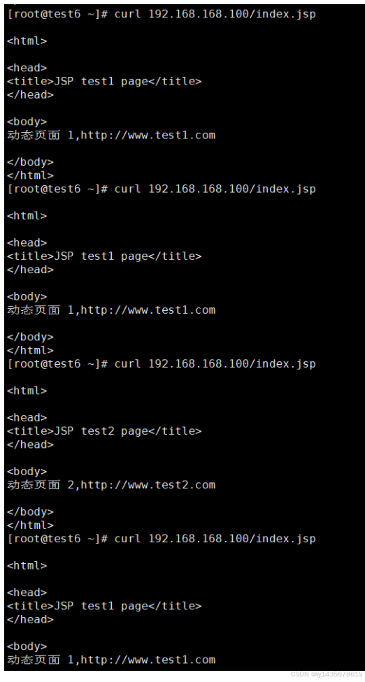
curl 192.168.168.100

nginx1 and nginx2 configure layer 7 proxy to send tomcat
vim /usr/local/nginx/conf/nginx.conf
#keepalive_timeout  0;
keepalive_timeout  65;
upstream tomcat {
    server 192.168.168.40:8080 weight=2;
    server 192.168.168.90:8080 weight=1;
            }
#gzip  on;

server {
    listen       80;
    server_name  localhost;
#charset koi8-r;

#access_log  logs/host.access.log  main;
location ~ .*.jsp$ {
proxy_pass http://tomcat;
proxy_set_header HOST $host;
proxy_set_header X-Real-IP $remote_addr;
proxy_set_header X-Forwarded-For $proxy_add_x_forwarded_for;
}
vim /usr/local/tomcat/conf/server.xml
 <Host name="localhost" appBase="webapps" unpackWARs="true" autoDeploy="true" xmlValidation="false" xmlNamespaceAware="false">
    <Context docBase="/usr/local/tomcat/webapps/test" path="" reloadable="true" />
mkdir -p /usr/local/tomcat/webapps/test
cd /usr/local/tomcat/webapps/test
vim index.jsp
<%@ page language="java" import="java.util.*" pageEncoding="UTF-8"%>
<html>

<head>
<title>JSP test1 page</title>
</head>

<body>
<% out.println("动态页面 1,http://www.test1.com");%>
</body>
</html>
cd /usr/local/tomcat/bin/
./shutdown.sh
./startup.sh
netstat -antp | grep 8080
vim /usr/local/tomcat/conf/server.xml
 <Host name="localhost" appBase="webapps" unpackWARs="true" autoDeploy="true" xmlValidation="false" xmlNamespaceAware="false">
    <Context docBase="/usr/local/tomcat/webapps/test" path="" reloadable="true" />
mkdir -p /usr/local/tomcat/webapps/test
cd /usr/local/tomcat/webapps/test
vim index.jsp
<%@ page language="java" import="java.util.*" pageEncoding="UTF-8"%>
<html>

<head>
<title>JSP test2 page</title>
</head>

<body>
<% out.println("动态页面 2,http://www.test2.com");%>
</body>
</html>
cd /usr/local/tomcat/bin/
./shutdown.sh
./startup.sh
netstat -antp | grep 8080
Layer 2 forwarding only changes the MAC header.
Data link layer forwarding does not change the IP header, but only changes the MAC header, and forwards the data packet to the backend RS server. Since the target IP of the data packet received by RS is still VIP, in order to ensure that RS can correctly process the data packet instead of discarding it, VIP must be configured on the loopback network card (lo) of RS. In this way, RS will think that this VIP is its own IP and can process this request. ----- It is equivalent to its own address request, and then sent to all hosts through arp broadcast. It reaches the client by shielding the virtual host.
Preventing ARP table disorder: If VIP is set on the RS's egress network card, RS will respond to the client's ARP request, which may cause the ARP table of the client or gateway to be disordered, thus affecting the normal operation of the entire load balancing system. By configuring VIP on the lo interface, RS can be prevented from responding to ARP requests, thereby maintaining a stable network environment.
The role of configuring lo (local loopback address) as VIP (Virtual IP) address on RS (Real Server) server is mainly based on the specific requirements and implementation mechanism of load balancing technology (such as LVS-DR mode). The following is a detailed role analysis:
In summary, the main purpose of configuring lo as the VIP address on the RS server is to ensure that the RS can receive and process IP packets with the target address as VIP, while avoiding confusion in ARP requests and responses, and improving the security and stability of the system. In addition, this configuration method also helps to simplify the configuration and management process.
A loopback interface is a special network interface that is used as a virtual network interface in the computer's network protocol stack. The main purpose of a loopback interface is to allow a system to communicate with itself over the network without going through any physical network interface. This communication method is called loopback or circular.
A network interface is a device or software in a computer system that is connected to a computer network. It provides a communication interface between the computer and the network and acts as a bridge between the computer and the network. The following is a specific definition and related information of a network interface:
There are many types of network interfaces, each with its own characteristics and applicable scenarios:
In summary, the network interface is a key component for communication between computers and networks. It enables data transmission and communication between computers and networks through physical connections or wireless signals. Different types of network interfaces are suitable for different scenarios and applications, providing important support for communication between computers and networks.
How to solve the keepalive split-brain problem?

I have devoted myself to the research of technology for more than 30 years. I am proficient in various languages such as Java, Linux, JavaScript, PHP, CSS, etc. I have made many contributions in the field of open source. I have established a developer documentation site to share some problems in technology development for everyone to read.

