Mi informacion de contacto
Correo[email protected]
2024-07-12
한어Русский языкEnglishFrançaisIndonesianSanskrit日本語DeutschPortuguêsΕλληνικάespañolItalianoSuomalainenLatina
(1) Como se muestra en la siguiente figura.
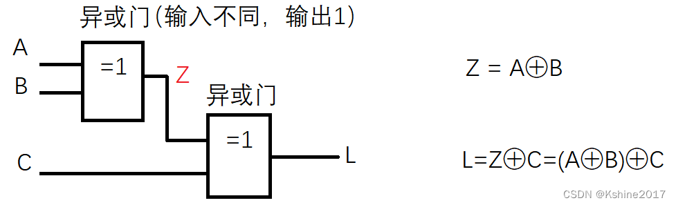
(2) Enumere la tabla de verdad
| A | B | C | O | yo |
|---|---|---|---|---|
| 0 | 0 | 0 | 0 | 0 |
| 0 | 0 | 1 | 0 | 1 |
| 0 | 1 | 0 | 1 | 1 |
| 0 | 1 | 1 | 1 | 0 |
| 1 | 0 | 0 | 1 | 1 |
| 1 | 0 | 1 | 1 | 0 |
| 1 | 1 | 0 | 0 | 0 |
| 1 | 1 | 1 | 0 | 1 |
(3) AnalizarCircuito de paridad imparFunción.
(1) Sobre la base del circuito de paridad impar, agregando un inversor al extremo de salida, podemos obtenerCircuito de paridad uniforme。
| A | B | C | X | Y | O |
|---|---|---|---|---|---|
| 0 | 0 | 0 | 0 | 0 | 0 |
| 0 | 0 | 1 | 0 | 0 | 1 |
| 0 | 1 | 0 | 0 | 1 | 0 |
| 0 | 1 | 1 | 0 | 1 | 1 |
| 1 | 0 | 0 | 1 | 1 | 1 |
| 1 | 0 | 1 | 1 | 1 | 0 |
| 1 | 1 | 0 | 1 | 0 | 1 |
| 1 | 1 | 1 | 1 | 0 | 0 |
necesidad.
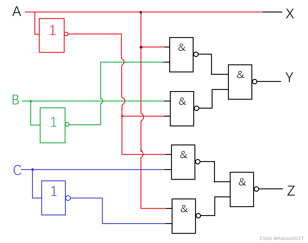
(1) Utilice 2 entradaspuerta NAND,inversor.
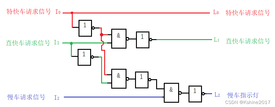
(2) Luz indicadora n.° 1, luz indicadora de llegada del tren expreso. Alta prioridad.
(3) Luz indicadora n.° 2, tren expreso directo que ingresa a la luz indicadora de la estación. En prioridad.
(4) Luz indicadora n.° 3, tren lento entrando en la luz indicadora de la estación. Baja prioridad.
(5) Como máximo puede haber una luz indicadora encendida al mismo tiempo.
Definir variables de entrada y salida.
(1) señal de entrada, I 0 petición exprés, I 1 petición exprés directa, I 2 petición tren de cercanías I_0 petición exprés, I_1 petición exprés directo, I_2 petición tren de cercaníasI0petición expresa,I1Solo solicítalo rápidamente,I2Solicitud de tren lento . 1 significa que hay una solicitud entrante, 0 significa que no hay ninguna solicitud entrante.
(2) señal de salida, L 0 indicador luminoso de parada exprés, L 1 indicador luminoso de parada exprés directa, L 2 indicador luminoso de parada de tren de cercanías L_0 indicador luminoso de parada exprés, L_1 indicador luminoso de parada rápida directa, L_2 indicador luminoso de parada de tren de cercaníasyo0Luz de llegada exprés,yo1Luz indicadora de parada directa,yo2Luz indicadora de llegada de tren lento . 1 significa que la luz está encendida, 0 significa que la luz está apagada.
Mesa de la verdad.
| ingresar | producción | ||||
| Yo_0 | Yo_1 | Yo_2 | L_0 | L_1 | L_2 |
| 0 | 0 | 0 | 0 | 0 | 0 |
| 1 | X | X | 1 | 0 | 0 |
| 0 | 1 | X | 0 | 1 | 0 |
| 0 | 0 | 1 | 0 | 0 | 1 |
Listar expresiones lógicas
L0 = yo0 L_0 = yo_0yo0=I0
L 1 = I 0 ‾ ⋅ I 1 L_1 = línea superior{I_0}·I_1yo1=I0⋅I1
L 2 = I 0 ‾ ⋅ I 1 ‾ ⋅ I 2 L_2 = línea superior{I_0}·línea superior{I_1}·I_2yo2=I0⋅I1⋅I2
Convierta a formato NAND según sea necesario.
L0 = yo0 L_0 = yo_0yo0=I0
L 1 = I 0 ‾ ⋅ I 1 ‾ ‾ L_1 = línea superior{línea superior{línea superior{I_0}·I_1}}yo1=I0⋅I1
L 2 = I 0 ‾ ⋅ I 1 ‾ ‾ ‾ ⋅ I 2 ‾ ‾ L_2 =sobrelínea{sobrelínea{sobrelínea{sobrelínea{sobrelínea{I_0}·sobrelínea{I_1}}}·I_2}}yo2=I0⋅I1⋅I2
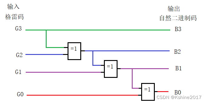
Dibuja un diagrama lógico.
(1) Un chip 74HC00 contiene cuatro puertas CMOS NAND de 2 entradas.
(2) Un chip 74HC04 contiene 6 inversores CMOS.
necesidad.
(1) Se puede utilizar cualquier circuito de puerta lógica.
(2) Código Gray de 4 bits, convertido en código binario natural.
Definir variables de entrada y salida.
(1) Variables de entrada, sol 3, sol 2, sol 1, sol 0 sol_3, sol_2, sol_1, sol_0GRAMORAMORAMORAMORAMORAMORAMORAMORAMORAMORAMORAMORAMORAMORAMORAMORAMORAMORAMORAMORAMORAMORAMORAMORAMORAMORAMORAMORAMORAMORAMORAMORAMORAMORAMORAMORAMORAMORAMORAMORAMORAMORAMORAMORAMORAMORAMORAMORAMORAMO3,GRAMORAMORAMORAMORAMORAMORAMORAMORAMORAMORAMORAMORAMORAMORAMORAMORAMORAMORAMORAMORAMORAMORAMORAMORAMORAMORAMORAMORAMORAMORAMORAMORAMORAMORAMORAMORAMORAMORAMORAMORAMORAMORAMORAMORAMORAMORAMORAMORAMORAMO2,GRAMORAMORAMORAMORAMORAMORAMORAMORAMORAMORAMORAMORAMORAMORAMORAMORAMORAMORAMORAMORAMORAMORAMORAMORAMORAMORAMORAMORAMORAMORAMORAMORAMORAMORAMORAMORAMORAMORAMORAMORAMORAMORAMORAMORAMORAMORAMORAMORAMORAMO1,GRAMORAMORAMORAMORAMORAMORAMORAMORAMORAMORAMORAMORAMORAMORAMORAMORAMORAMORAMORAMORAMORAMORAMORAMORAMORAMORAMORAMORAMORAMORAMORAMORAMORAMORAMORAMORAMORAMORAMORAMORAMORAMORAMORAMORAMORAMORAMORAMORAMORAMO0。
(2) Variables de salida, B3, B2, B1, B0 B_3, B_2, B_1, B_0B3,B2,B1,B0。
Enumera la tabla de verdad.
| ingresar | producción | ||||||
| G_3 | G_2 | G_1 | G_0 | B_3 | B_2 | B_1 | B_0 |
| 0 | 0 | 0 | 0 | 0 | 0 | 0 | 0 |
| 0 | 0 | 0 | 1 | 0 | 0 | 0 | 1 |
| 0 | 0 | 1 | 1 | 0 | 0 | 1 | 0 |
| 0 | 0 | 1 | 0 | 0 | 0 | 1 | 1 |
| 0 | 1 | 1 | 0 | 0 | 1 | 0 | 0 |
| 0 | 1 | 1 | 1 | 0 | 1 | 0 | 1 |
| 0 | 1 | 0 | 1 | 0 | 1 | 1 | 0 |
| 0 | 1 | 0 | 0 | 0 | 1 | 1 | 1 |
| 1 | 1 | 0 | 0 | 1 | 0 | 0 | 0 |
| 1 | 1 | 0 | 1 | 1 | 0 | 0 | 1 |
| 1 | 1 | 1 | 1 | 1 | 0 | 1 | 0 |
| 1 | 1 | 1 | 0 | 1 | 0 | 1 | 1 |
| 1 | 0 | 1 | 0 | 1 | 1 | 0 | 0 |
| 1 | 0 | 1 | 1 | 1 | 1 | 0 | 1 |
| 1 | 0 | 0 | 1 | 1 | 1 | 1 | 0 |
| 1 | 0 | 0 | 0 | 1 | 1 | 1 | 1 |
Dibuja un mapa de Karnaugh basado en la tabla de verdad.
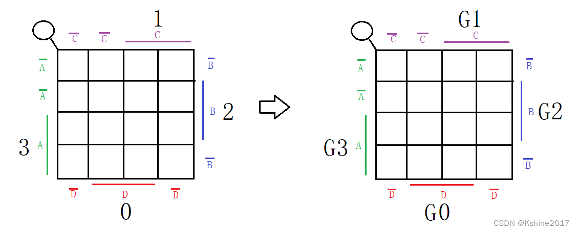
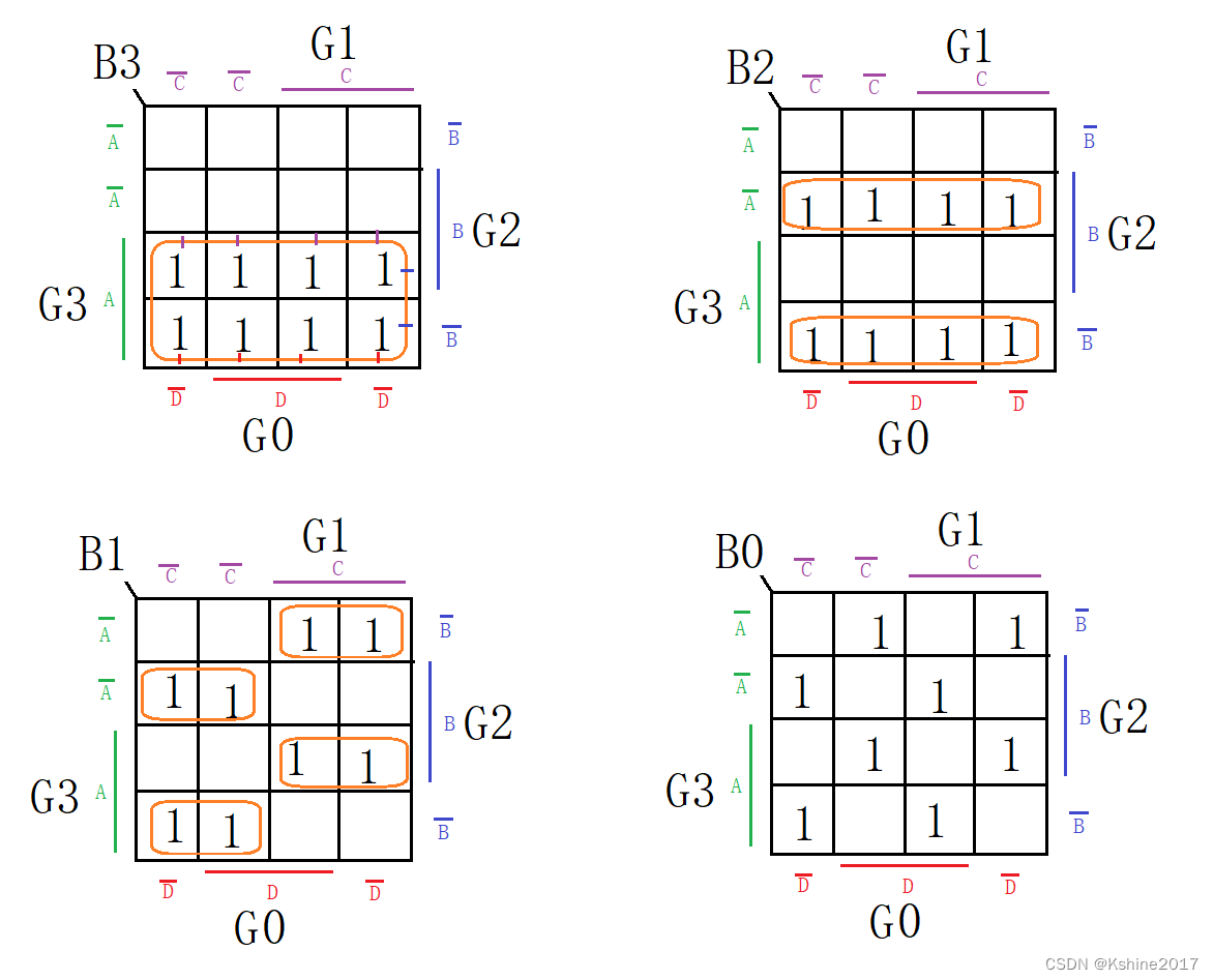
Enumera expresiones lógicas.
B3 = G3 B_3 = G_3B3=GRAMORAMORAMORAMORAMORAMORAMORAMORAMORAMORAMORAMORAMORAMORAMORAMORAMORAMORAMORAMORAMORAMORAMORAMORAMORAMORAMORAMORAMORAMORAMORAMORAMORAMORAMORAMORAMORAMORAMORAMORAMORAMORAMORAMORAMORAMORAMORAMORAMORAMO3
B 2 = G 3 ‾ ⋅ G 2 + G 3 ⋅ G 2 ‾ = G 3 ⊕ G 2 B_2 = línea superior{G_3}·G_2 + G_3·línea superior{G_2}=G_3⊕G_2B2=GRAMORAMORAMORAMORAMORAMORAMORAMORAMORAMORAMORAMORAMORAMORAMORAMORAMORAMORAMORAMORAMORAMORAMORAMORAMORAMORAMORAMORAMORAMORAMORAMORAMORAMORAMORAMORAMORAMORAMORAMORAMORAMORAMORAMORAMORAMORAMORAMORAMORAMO3⋅GRAMORAMORAMORAMORAMORAMORAMORAMORAMORAMORAMORAMORAMORAMORAMORAMORAMORAMORAMORAMORAMORAMORAMORAMORAMORAMORAMORAMORAMORAMORAMORAMORAMORAMORAMORAMORAMORAMORAMORAMORAMORAMORAMORAMORAMORAMORAMORAMORAMORAMO2+GRAMORAMORAMORAMORAMORAMORAMORAMORAMORAMORAMORAMORAMORAMORAMORAMORAMORAMORAMORAMORAMORAMORAMORAMORAMORAMORAMORAMORAMORAMORAMORAMORAMORAMORAMORAMORAMORAMORAMORAMORAMORAMORAMORAMORAMORAMORAMORAMORAMORAMO3⋅GRAMORAMORAMORAMORAMORAMORAMORAMORAMORAMORAMORAMORAMORAMORAMORAMORAMORAMORAMORAMORAMORAMORAMORAMORAMORAMORAMORAMORAMORAMORAMORAMORAMORAMORAMORAMORAMORAMORAMORAMORAMORAMORAMORAMORAMORAMORAMORAMORAMORAMO2=GRAMORAMORAMORAMORAMORAMORAMORAMORAMORAMORAMORAMORAMORAMORAMORAMORAMORAMORAMORAMORAMORAMORAMORAMORAMORAMORAMORAMORAMORAMORAMORAMORAMORAMORAMORAMORAMORAMORAMORAMORAMORAMORAMORAMORAMORAMORAMORAMORAMORAMO3⊕GRAMORAMORAMORAMORAMORAMORAMORAMORAMORAMORAMORAMORAMORAMORAMORAMORAMORAMORAMORAMORAMORAMORAMORAMORAMORAMORAMORAMORAMORAMORAMORAMORAMORAMORAMORAMORAMORAMORAMORAMORAMORAMORAMORAMORAMORAMORAMORAMORAMORAMO2
B 1 = G 3 ‾ G 2 G 1 ‾ + G 3 G 2 ‾ G 1 ‾ + G 3 ‾ G 2 ‾ G 1 + G 3 G 2 G 1 = ( G 3 G 2 ‾ + G 3 ‾ G 2 ) G 1 ‾ + ( G 3 G 2 ‾ + G 3 ‾ G 2 ) ‾ G 1 = G 3 ⊕ G 2 ⊕ G 1 B_1 = sobrelínea{G_3}G_2sobrelínea{G_1}+G_3sobrelínea{G_2}sobrelínea{G_1}+sobrelínea{G_3}sobrelínea{G_2}G_1+G_3G_2G_1=(G_3sobrelínea{G_2}+sobrelínea{G_3}G_2)sobrelínea{G_1}+sobrelínea{(G_3sobrelínea{G_2}+sobrelínea{G_3}G_2)}G_1=G_3⊕G_2⊕G_1B1=GRAMORAMORAMORAMORAMORAMORAMORAMORAMORAMORAMORAMORAMORAMORAMORAMORAMORAMORAMORAMORAMORAMORAMORAMORAMORAMORAMORAMORAMORAMORAMORAMORAMORAMORAMORAMORAMORAMORAMORAMORAMORAMORAMORAMORAMORAMORAMORAMORAMORAMO3GRAMORAMORAMORAMORAMORAMORAMORAMORAMORAMORAMORAMORAMORAMORAMORAMORAMORAMORAMORAMORAMORAMORAMORAMORAMORAMORAMORAMORAMORAMORAMORAMORAMORAMORAMORAMORAMORAMORAMORAMORAMORAMORAMORAMORAMORAMORAMORAMORAMORAMO2GRAMORAMORAMORAMORAMORAMORAMORAMORAMORAMORAMORAMORAMORAMORAMORAMORAMORAMORAMORAMORAMORAMORAMORAMORAMORAMORAMORAMORAMORAMORAMORAMORAMORAMORAMORAMORAMORAMORAMORAMORAMORAMORAMORAMORAMORAMORAMORAMORAMORAMO1+GRAMORAMORAMORAMORAMORAMORAMORAMORAMORAMORAMORAMORAMORAMORAMORAMORAMORAMORAMORAMORAMORAMORAMORAMORAMORAMORAMORAMORAMORAMORAMORAMORAMORAMORAMORAMORAMORAMORAMORAMORAMORAMORAMORAMORAMORAMORAMORAMORAMORAMO3GRAMORAMORAMORAMORAMORAMORAMORAMORAMORAMORAMORAMORAMORAMORAMORAMORAMORAMORAMORAMORAMORAMORAMORAMORAMORAMORAMORAMORAMORAMORAMORAMORAMORAMORAMORAMORAMORAMORAMORAMORAMORAMORAMORAMORAMORAMORAMORAMORAMORAMO2GRAMORAMORAMORAMORAMORAMORAMORAMORAMORAMORAMORAMORAMORAMORAMORAMORAMORAMORAMORAMORAMORAMORAMORAMORAMORAMORAMORAMORAMORAMORAMORAMORAMORAMORAMORAMORAMORAMORAMORAMORAMORAMORAMORAMORAMORAMORAMORAMORAMORAMO1+GRAMORAMORAMORAMORAMORAMORAMORAMORAMORAMORAMORAMORAMORAMORAMORAMORAMORAMORAMORAMORAMORAMORAMORAMORAMORAMORAMORAMORAMORAMORAMORAMORAMORAMORAMORAMORAMORAMORAMORAMORAMORAMORAMORAMORAMORAMORAMORAMORAMORAMO3GRAMORAMORAMORAMORAMORAMORAMORAMORAMORAMORAMORAMORAMORAMORAMORAMORAMORAMORAMORAMORAMORAMORAMORAMORAMORAMORAMORAMORAMORAMORAMORAMORAMORAMORAMORAMORAMORAMORAMORAMORAMORAMORAMORAMORAMORAMORAMORAMORAMORAMO2GRAMORAMORAMORAMORAMORAMORAMORAMORAMORAMORAMORAMORAMORAMORAMORAMORAMORAMORAMORAMORAMORAMORAMORAMORAMORAMORAMORAMORAMORAMORAMORAMORAMORAMORAMORAMORAMORAMORAMORAMORAMORAMORAMORAMORAMORAMORAMORAMORAMORAMO1+GRAMORAMORAMORAMORAMORAMORAMORAMORAMORAMORAMORAMORAMORAMORAMORAMORAMORAMORAMORAMORAMORAMORAMORAMORAMORAMORAMORAMORAMORAMORAMORAMORAMORAMORAMORAMORAMORAMORAMORAMORAMORAMORAMORAMORAMORAMORAMORAMORAMORAMO3GRAMORAMORAMORAMORAMORAMORAMORAMORAMORAMORAMORAMORAMORAMORAMORAMORAMORAMORAMORAMORAMORAMORAMORAMORAMORAMORAMORAMORAMORAMORAMORAMORAMORAMORAMORAMORAMORAMORAMORAMORAMORAMORAMORAMORAMORAMORAMORAMORAMORAMO2GRAMORAMORAMORAMORAMORAMORAMORAMORAMORAMORAMORAMORAMORAMORAMORAMORAMORAMORAMORAMORAMORAMORAMORAMORAMORAMORAMORAMORAMORAMORAMORAMORAMORAMORAMORAMORAMORAMORAMORAMORAMORAMORAMORAMORAMORAMORAMORAMORAMORAMO1=(GRAMORAMORAMORAMORAMORAMORAMORAMORAMORAMORAMORAMORAMORAMORAMORAMORAMORAMORAMORAMORAMORAMORAMORAMORAMORAMORAMORAMORAMORAMORAMORAMORAMORAMORAMORAMORAMORAMORAMORAMORAMORAMORAMORAMORAMORAMORAMORAMORAMORAMO3GRAMORAMORAMORAMORAMORAMORAMORAMORAMORAMORAMORAMORAMORAMORAMORAMORAMORAMORAMORAMORAMORAMORAMORAMORAMORAMORAMORAMORAMORAMORAMORAMORAMORAMORAMORAMORAMORAMORAMORAMORAMORAMORAMORAMORAMORAMORAMORAMORAMORAMO2+GRAMORAMORAMORAMORAMORAMORAMORAMORAMORAMORAMORAMORAMORAMORAMORAMORAMORAMORAMORAMORAMORAMORAMORAMORAMORAMORAMORAMORAMORAMORAMORAMORAMORAMORAMORAMORAMORAMORAMORAMORAMORAMORAMORAMORAMORAMORAMORAMORAMORAMO3GRAMORAMORAMORAMORAMORAMORAMORAMORAMORAMORAMORAMORAMORAMORAMORAMORAMORAMORAMORAMORAMORAMORAMORAMORAMORAMORAMORAMORAMORAMORAMORAMORAMORAMORAMORAMORAMORAMORAMORAMORAMORAMORAMORAMORAMORAMORAMORAMORAMORAMO2)GRAMORAMORAMORAMORAMORAMORAMORAMORAMORAMORAMORAMORAMORAMORAMORAMORAMORAMORAMORAMORAMORAMORAMORAMORAMORAMORAMORAMORAMORAMORAMORAMORAMORAMORAMORAMORAMORAMORAMORAMORAMORAMORAMORAMORAMORAMORAMORAMORAMORAMO1+(GRAMORAMORAMORAMORAMORAMORAMORAMORAMORAMORAMORAMORAMORAMORAMORAMORAMORAMORAMORAMORAMORAMORAMORAMORAMORAMORAMORAMORAMORAMORAMORAMORAMORAMORAMORAMORAMORAMORAMORAMORAMORAMORAMORAMORAMORAMORAMORAMORAMORAMO3GRAMORAMORAMORAMORAMORAMORAMORAMORAMORAMORAMORAMORAMORAMORAMORAMORAMORAMORAMORAMORAMORAMORAMORAMORAMORAMORAMORAMORAMORAMORAMORAMORAMORAMORAMORAMORAMORAMORAMORAMORAMORAMORAMORAMORAMORAMORAMORAMORAMORAMO2+GRAMORAMORAMORAMORAMORAMORAMORAMORAMORAMORAMORAMORAMORAMORAMORAMORAMORAMORAMORAMORAMORAMORAMORAMORAMORAMORAMORAMORAMORAMORAMORAMORAMORAMORAMORAMORAMORAMORAMORAMORAMORAMORAMORAMORAMORAMORAMORAMORAMORAMO3GRAMORAMORAMORAMORAMORAMORAMORAMORAMORAMORAMORAMORAMORAMORAMORAMORAMORAMORAMORAMORAMORAMORAMORAMORAMORAMORAMORAMORAMORAMORAMORAMORAMORAMORAMORAMORAMORAMORAMORAMORAMORAMORAMORAMORAMORAMORAMORAMORAMORAMO2)GRAMORAMORAMORAMORAMORAMORAMORAMORAMORAMORAMORAMORAMORAMORAMORAMORAMORAMORAMORAMORAMORAMORAMORAMORAMORAMORAMORAMORAMORAMORAMORAMORAMORAMORAMORAMORAMORAMORAMORAMORAMORAMORAMORAMORAMORAMORAMORAMORAMORAMO1=GRAMORAMORAMORAMORAMORAMORAMORAMORAMORAMORAMORAMORAMORAMORAMORAMORAMORAMORAMORAMORAMORAMORAMORAMORAMORAMORAMORAMORAMORAMORAMORAMORAMORAMORAMORAMORAMORAMORAMORAMORAMORAMORAMORAMORAMORAMORAMORAMORAMORAMO3⊕GRAMORAMORAMORAMORAMORAMORAMORAMORAMORAMORAMORAMORAMORAMORAMORAMORAMORAMORAMORAMORAMORAMORAMORAMORAMORAMORAMORAMORAMORAMORAMORAMORAMORAMORAMORAMORAMORAMORAMORAMORAMORAMORAMORAMORAMORAMORAMORAMORAMORAMO2⊕GRAMORAMORAMORAMORAMORAMORAMORAMORAMORAMORAMORAMORAMORAMORAMORAMORAMORAMORAMORAMORAMORAMORAMORAMORAMORAMORAMORAMORAMORAMORAMORAMORAMORAMORAMORAMORAMORAMORAMORAMORAMORAMORAMORAMORAMORAMORAMORAMORAMORAMO1
B0 = G3 ⊕G2 ⊕G1 ⊕G0 B_0=G_3⊕G_2⊕G_1⊕G_0B0=GRAMORAMORAMORAMORAMORAMORAMORAMORAMORAMORAMORAMORAMORAMORAMORAMORAMORAMORAMORAMORAMORAMORAMORAMORAMORAMORAMORAMORAMORAMORAMORAMORAMORAMORAMORAMORAMORAMORAMORAMORAMORAMORAMORAMORAMORAMORAMORAMORAMORAMO3⊕GRAMORAMORAMORAMORAMORAMORAMORAMORAMORAMORAMORAMORAMORAMORAMORAMORAMORAMORAMORAMORAMORAMORAMORAMORAMORAMORAMORAMORAMORAMORAMORAMORAMORAMORAMORAMORAMORAMORAMORAMORAMORAMORAMORAMORAMORAMORAMORAMORAMORAMO2⊕GRAMORAMORAMORAMORAMORAMORAMORAMORAMORAMORAMORAMORAMORAMORAMORAMORAMORAMORAMORAMORAMORAMORAMORAMORAMORAMORAMORAMORAMORAMORAMORAMORAMORAMORAMORAMORAMORAMORAMORAMORAMORAMORAMORAMORAMORAMORAMORAMORAMORAMO1⊕GRAMORAMORAMORAMORAMORAMORAMORAMORAMORAMORAMORAMORAMORAMORAMORAMORAMORAMORAMORAMORAMORAMORAMORAMORAMORAMORAMORAMORAMORAMORAMORAMORAMORAMORAMORAMORAMORAMORAMORAMORAMORAMORAMORAMORAMORAMORAMORAMORAMORAMO0
Dibuja un diagrama lógico.
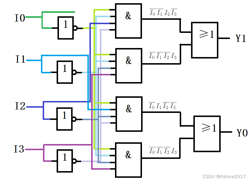
| Yo 0 Yo_0I0 | Yo 1 Yo_1I1 | Yo 2 Yo_2I2 | Yo 3 Yo_3I3 | Y1Y_1Y1 | Y0Y_0Y0 |
|---|---|---|---|---|---|
| 1 | 0 | 0 | 0 | 0 | 0 |
| 0 | 1 | 0 | 0 | 0 | 1 |
| 0 | 0 | 1 | 0 | 1 | 0 |
| 0 | 0 | 0 | 1 | 1 | 1 |
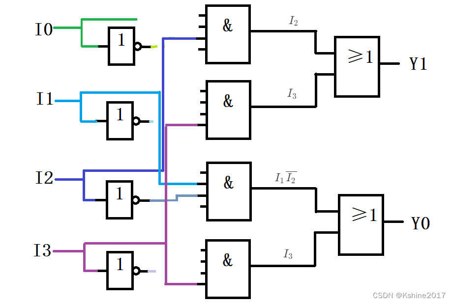
| Yo 0 Yo_0I0 | Yo 1 Yo_1I1 | Yo 2 Yo_2I2 | Yo 3 Yo_3I3 | Y1Y_1Y1 | Y0Y_0Y0 |
|---|---|---|---|---|---|
| 1 | 0 | 0 | 0 | 0 | 0 |
| X | 1 | 0 | 0 | 0 | 1 |
| X | X | 1 | 0 | 1 | 0 |
| X | X | X | 1 | 1 | 1 |
| S 9 S_9S9 | S 8 S_8S8 | S7 S_7S7 | S6 S_6S6 | S 5 S_5S5 | S 4 S_4S4 | S3S_3S3 | S2S_2S2 | S1S_1S1 | S0S_0S0 | Automóvil club británicoA | CAMA Y DESAYUNOB | C.C.C | DDD | GSGSGS | |
|---|---|---|---|---|---|---|---|---|---|---|---|---|---|---|---|
| 1 | 1 | 1 | 1 | 1 | 1 | 1 | 1 | 1 | 1 | 0 | 0 | 0 | 0 | 0 | |
| 1 | 1 | 1 | 1 | 1 | 1 | 1 | 1 | 1 | 0 | 0 | 0 | 0 | 0 | 1 | |
| 1 | 1 | 1 | 1 | 1 | 1 | 1 | 1 | 0 | 1 | 0 | 0 | 0 | 1 | 1 | |
| 1 | 1 | 1 | 1 | 1 | 1 | 1 | 0 | 1 | 1 | 0 | 0 | 1 | 0 | 1 | |
| 1 | 1 | 1 | 1 | 1 | 1 | 0 | 1 | 1 | 1 | 0 | 0 | 1 | 1 | 1 | |
| 1 | 1 | 1 | 1 | 1 | 0 | 1 | 1 | 1 | 1 | 0 | 1 | 0 | 0 | 1 | |
| 1 | 1 | 1 | 1 | 0 | 1 | 1 | 1 | 1 | 1 | 0 | 1 | 0 | 1 | 1 | |
| 1 | 1 | 1 | 0 | 1 | 1 | 1 | 1 | 1 | 1 | 0 | 1 | 1 | 0 | 1 | |
| 1 | 1 | 0 | 1 | 1 | 1 | 1 | 1 | 1 | 1 | 0 | 1 | 1 | 1 | 1 | |
| 1 | 0 | 1 | 1 | 1 | 1 | 1 | 1 | 1 | 1 | 1 | 0 | 0 | 0 | 1 | |
| 0 | 1 | 1 | 1 | 1 | 1 | 1 | 1 | 1 | 1 | 1 | 0 | 0 | 1 | 1 |
Típico: codificador de prioridad CD4532 (descontinuado)

El codificador de prioridad I 7 tiene la prioridad más alta y I 0 tiene la prioridad más baja. El codificador de prioridad I_7 tiene la prioridad más alta y I_0 tiene la prioridad más baja.codificador de prioridadI7más alta prioridad,I0La prioridad más baja.
Cuando EI=1, cuando todas las entradas son de nivel bajo, noprioridad más baja Ingrese un nivel alto y emita 000 en este momento. En este momento EO=1.
Sólo cuando EI=1 y todas las entradas son 0, EO=1. Dedicado a la conexión en cascada de EI con otro dispositivo.
Cuando EI=1, al menos uno de los terminales de entrada es de nivel alto 1 y GS=1.
Consulte el libro para conocer expresiones lógicas específicas y diagramas de bloques lógicos.
| EI permite codificar EI permite codificarmiICodificación permitida | Yo 7 Yo_7I7 | Yo 6 Yo_6I6 | Yo 5 Yo_5I5 | Yo 4 Yo_4I4 | Yo 3 Yo_3I3 | Yo 2 Yo_2I2 | Yo 1 Yo_1I1 | Yo 0 Yo_0I0 | Y2Y_2Y2 | Y1Y_1Y1 | Y0Y_0Y0 | GS tiene entrada 1 GS tiene entrada 1GShay entrada1 | EO ingresa todos los 0 EO ingresa todos los 0EOIngresar todo0 | |
|---|---|---|---|---|---|---|---|---|---|---|---|---|---|---|
| 0 | X | X | X | X | X | X | X | X | 0 | 0 | 0 | 0 | 0 | |
| 1 | 1 | X | X | X | X | X | X | X | 1 | 1 | 1 | 1 | 0 | |
| 1 | 0 | 1 | X | X | X | X | X | X | 1 | 1 | 0 | 1 | 0 | |
| 1 | 0 | 0 | 1 | X | X | X | X | X | 1 | 0 | 1 | 1 | 0 | |
| 1 | 0 | 0 | 0 | 1 | X | X | X | X | 1 | 0 | 0 | 1 | 0 | |
| 1 | 0 | 0 | 0 | 0 | 1 | X | X | X | 0 | 1 | 1 | 1 | 0 | |
| 1 | 0 | 0 | 0 | 0 | 0 | 1 | X | X | 0 | 1 | 0 | 1 | 0 | |
| 1 | 0 | 0 | 0 | 0 | 0 | 0 | 1 | X | 0 | 0 | 1 | 1 | 0 | |
| 1 | 0 | 0 | 0 | 0 | 0 | 0 | 0 | 1 | 0 | 0 | 0 | 1 | 0 | |
| 1 | 0 | 0 | 0 | 0 | 0 | 0 | 0 | 0 | 0 | 0 | 0 | 0 | 1 |

Cuando EI 1 = 0, el segmento 1 está deshabilitado. Y 2 Y 1 Y 0 = = 000 , GS 1 = 0 , EO 1 = 0 . EI 0 = 0, el chip 0 también está desactivado. Cuando EI_1=0, el segmento 1 está deshabilitado. Y_2Y_1Y_0==000, GS_1=0, EO_1=0. EI_0=0, el segmento 0 también está deshabilitado.cuandomiI1=0tiempo, película1Desactivado.Y2Y1Y0==000,GRAMORAMORAMORAMORAMORAMORAMORAMORAMORAMORAMORAMORAMORAMORAMORAMORAMORAMORAMORAMORAMORAMORAMORAMORAMORAMORAMORAMORAMORAMORAMORAMORAMORAMORAMORAMORAMORAMORAMORAMORAMORAMORAMORAMORAMORAMORAMORAMORAMORAMOS1=0,miOhhhhhhh1=0。miI0=0,pedazo0También discapacitado.
Cuando EI 1 = 1, se permite codificar el segmento 1. Si I 15 − I 8 = 000...000, entonces EO 1 = 1, entonces EI 0 = 1. El segmento 0 permite la codificación. Se puede ver que la codificación del segmento 1 tiene una prioridad más alta que la codificación del segmento 0. Cuando EI_1 = 1, se permite la codificación del segmento 1. Si I_ {15} - I_8 = 000...000, entonces EO_1 =. 1, entonces EI_0=1. El segmento 0 permite la codificación.Se puede ver que la prioridad de la codificación del segmento 1 es mayor que la de la codificación del segmento 0.cuandomiI1=1tiempo, película1Se permite la codificación siI15−I8=000...000,en este momentomiOhhhhhhh1=1,de este modomiI0=1 .pedazo0 Se permite la codificación.Se puede ver que la película1La codificación tiene prioridad sobre los cortes0codificación。
Cuando EI 1 = 1, se permite la codificación en el segmento 1. Si I 15 − I 8 tiene al menos un 1, entonces EO 1 = 0, por lo que EI 0 = 0, y la codificación está prohibida en el segmento 0. Cuando EI_1=1, se permite la codificación en el segmento 1. Si I_{15} - I_8 tiene al menos un 1, entonces EO_1=0, por lo que EI_0=0, la codificación está prohibida en el segmento 0.cuandomiI1=1tiempo, película1Se permite la codificación siI15−I8al menos uno1,en este momentomiOhhhhhhh1=0,de este modomiI0=0,pedazo0La codificación está prohibida.
| EI 1 permite codificar EI_1 permite codificarmiI1Codificación permitida | EI 0 permite codificar EI_0 permite codificarmiI0Codificación permitida | yo 15 yo_{15}I15 | Yo 14 Yo_{14}I14 | Yo 13 Yo_{13}I13 | Yo 12 Yo_{12}I12 | yo 11 yo_{11}I11 | yo 10 yo_{10}I10 | Yo 9 Yo_9I9 | Yo 8 Yo_8I8 | Yo 7 Yo_7I7 | Yo 6 Yo_6I6 | Yo 5 Yo_5I5 | Yo 4 Yo_4I4 | Yo 3 Yo_3I3 | Yo 2 Yo_2I2 | Yo 1 Yo_1I1 | Yo 0 Yo_0I0 | Y21Y2_1Y21 | Y11Y1_1Y11 | Y01Y0_1Y01 | Y20Y2_0Y20 | Y10Y1_0Y10 | Y00Y0_0Y00 | EO 1 Ingrese todos los 0 EO_1 Ingrese todos los 0miOhhhhhhh1Ingresar todo0 | EO 0 Ingrese todos los 0 EO_0 Ingrese todos los 0miOhhhhhhh0Ingresar todo0 | GS 1 tiene entrada 1 GS_1 tiene entrada 1GRAMORAMORAMORAMORAMORAMORAMORAMORAMORAMORAMORAMORAMORAMORAMORAMORAMORAMORAMORAMORAMORAMORAMORAMORAMORAMORAMORAMORAMORAMORAMORAMORAMORAMORAMORAMORAMORAMORAMORAMORAMORAMORAMORAMORAMORAMORAMORAMORAMORAMOS1hay entrada1 | GS 0 tiene entrada 0 GS_0 tiene entrada 0GRAMORAMORAMORAMORAMORAMORAMORAMORAMORAMORAMORAMORAMORAMORAMORAMORAMORAMORAMORAMORAMORAMORAMORAMORAMORAMORAMORAMORAMORAMORAMORAMORAMORAMORAMORAMORAMORAMORAMORAMORAMORAMORAMORAMORAMORAMORAMORAMORAMORAMOS0hay entrada0 | L 3 L_3yo3 | L2L_2yo2 | L1L1yo1 | L0L_0yo0 | |
|---|---|---|---|---|---|---|---|---|---|---|---|---|---|---|---|---|---|---|---|---|---|---|---|---|---|---|---|---|---|---|---|---|
| 0 (sección 1 deshabilitada) | EI 0 = EO 1 = 0 EI_0=EO_1=0miI0=miOhhhhhhh1=0(deshabilitado en el segmento 0) | X | X | X | X | X | X | X | X | X | X | X | X | X | X | X | X | 0 | 0 | 0 | 0 | 0 | 0 | 0 | 0 | 0 | 0 | 0 | 0 | 0 | 0 | |
| 1 | 0 | 1 | X | X | X | X | X | X | X | X | X | X | X | X | X | X | X | 1 | 1 | 1 | 0 | 0 | 0 | 0 | 0 | 1 (el chip 1 tiene entrada) | 0 | 1 L3 = GS1 L_3 = GS_1yo3=GRAMORAMORAMORAMORAMORAMORAMORAMORAMORAMORAMORAMORAMORAMORAMORAMORAMORAMORAMORAMORAMORAMORAMORAMORAMORAMORAMORAMORAMORAMORAMORAMORAMORAMORAMORAMORAMORAMORAMORAMORAMORAMORAMORAMORAMORAMORAMORAMORAMORAMOS1 | 1 L2 = Y2_1 L_2 = Y2_1yo2=Y21 | 1 L1 = Y11 L_1 = Y1_1yo1=Y11 | 1 L0 = Y01 L_0 = Y0_1yo0=Y01 | |
| 1 | 0 | 0 | 1 | X | X | X | X | X | X | X | X | X | X | X | X | X | X | 1 | 1 | 0 | 0 | 0 | 0 | 0 | 0 | 1 | 0 | 1 | 1 | 1 | 0 | |
| 1 | 0 | 0 | 0 | 1 | X | X | X | X | X | X | X | X | X | X | X | X | X | 1 | 0 | 1 | 0 | 0 | 0 | 0 | 0 | 1 | 0 | 1 | 1 | 0 | 1 | |
| 1 | 0 | 0 | 0 | 0 | 1 | X | X | X | X | X | X | X | X | X | X | X | X | 1 | 0 | 0 | 0 | 0 | 0 | 0 | 0 | 1 | 0 | 1 | 1 | 0 | 0 | |
| 1 | 0 | 0 | 0 | 0 | 0 | 1 | X | X | X | X | X | X | X | X | X | X | X | 0 | 1 | 1 | 0 | 0 | 0 | 0 | 0 | 1 | 0 | 1 | 0 | 1 | 1 | |
| 1 | 0 | 0 | 0 | 0 | 0 | 0 | 1 | X | X | X | X | X | X | X | X | X | X | 0 | 1 | 0 | 0 | 0 | 0 | 0 | 0 | 1 | 0 | 1 | 0 | 1 | 0 | |
| 1 | 0 | 0 | 0 | 0 | 0 | 0 | 0 | 1 | X | X | X | X | X | X | X | X | X | 0 | 0 | 1 | 0 | 0 | 0 | 0 | 0 | 1 | 0 | 1 | 0 | 0 | 1 | |
| 1 | 0 | 0 | 0 | 0 | 0 | 0 | 0 | 0 | 1 | X | X | X | X | X | X | X | X | 0 | 0 | 0 | 0 | 0 | 0 | 0 | 0 | 1 | 0 | 1 | 0 | 0 | 0 | |
| 1 | EI 0 = EO 1 = 1 EI_0=EO_1=1miI0=miOhhhhhhh1=1(pieza 0 obra) | 0 | 0 | 0 | 0 | 0 | 0 | 0 | 0 | 1 | X | X | X | X | X | X | X | 0 | 0 | 0 | 1 | 1 | 1 | 1 (la entrada del chip 1 es toda 0) | 0 | 0 (codificación no válida para el segmento 1) | 1 | 0 L3 = GS1 L_3 = GS_1yo3=GRAMORAMORAMORAMORAMORAMORAMORAMORAMORAMORAMORAMORAMORAMORAMORAMORAMORAMORAMORAMORAMORAMORAMORAMORAMORAMORAMORAMORAMORAMORAMORAMORAMORAMORAMORAMORAMORAMORAMORAMORAMORAMORAMORAMORAMORAMORAMORAMORAMORAMOS1 | 1 L2 = Y2_0 L_2 = Y2_0yo2=Y20 | 1 L1 = Y10 L_1 = Y1_0yo1=Y10 | 1 L0 = Y00 L_0 = Y0_0yo0=Y00 | |
| 1 | 1 | 0 | 0 | 0 | 0 | 0 | 0 | 0 | 0 | 0 | 1 | X | X | X | X | X | X | 0 | 0 | 0 | 1 | 1 | 0 | 1 | 0 | 0 | 1 | 0 | 1 | 1 | 0 | |
| 1 | 1 | 0 | 0 | 0 | 0 | 0 | 0 | 0 | 0 | 0 | 0 | 1 | X | X | X | X | X | 0 | 0 | 0 | 1 | 1 | 1 | 1 | 0 | 0 | 1 | 0 | 1 | 0 | 1 | |
| 1 | 1 | 0 | 0 | 0 | 0 | 0 | 0 | 0 | 0 | 0 | 0 | 0 | 1 | X | X | X | X | 0 | 0 | 0 | 1 | 1 | 1 | 1 | 0 | 0 | 1 | 0 | 1 | 0 | 0 | |
| 1 | 1 | 0 | 0 | 0 | 0 | 0 | 0 | 0 | 0 | 0 | 0 | 0 | 0 | 1 | X | X | X | 0 | 0 | 0 | 1 | 1 | 1 | 1 | 0 | 0 | 1 | 0 | 0 | 1 | 1 | |
| 1 | 1 | 0 | 0 | 0 | 0 | 0 | 0 | 0 | 0 | 0 | 0 | 0 | 0 | 0 | 1 | X | X | 0 | 0 | 0 | 1 | 1 | 1 | 1 | 0 | 0 | 1 | 0 | 0 | 1 | 0 | |
| 1 | 1 | 0 | 0 | 0 | 0 | 0 | 0 | 0 | 0 | 0 | 0 | 0 | 0 | 0 | 0 | 1 | X | 0 | 0 | 0 | 1 | 1 | 1 | 1 | 0 | 0 | 1 | 0 | 0 | 0 | 1 | |
| 1 | 1 | 0 | 0 | 0 | 0 | 0 | 0 | 0 | 0 | 0 | 0 | 0 | 0 | 0 | 0 | 0 | 1 | 0 | 0 | 0 | 1 | 1 | 1 | 1 | 0 | 0 | 1 | 0 | 0 | 0 | 0 | |
| 1 | 1 | 0 | 0 | 0 | 0 | 0 | 0 | 0 | 0 | 0 | 0 | 0 | 0 | 0 | 0 | 0 | 0 | 0 | 0 | 0 | 1 | 1 | 1 | 1 | 1 (la entrada del chip 0 es toda 0) | 0 | 0 (sección 0 codificación no válida) | 0 | 0 | 0 | 0 |

| ingresar | producción | |||||
| /MI | A_1 | A_0 | /Y_3 | /Y_2 | /Y_1 | /Y_0 |
| 1 prohibido | X | X | 1 | 1 | 1 | 1 |
| 0 habilitar | 0 | 0 | 1 | 1 | 1 | 0 bajo activo |
| 0 habilitar | 0 | 1 | 1 | 1 | 0 baja efectividad | 1 |
| 0 habilitar | 1 | 0 | 1 | 0 bajo activo | 1 | 1 |
| 0 habilitar | 1 | 1 | 0 bajo activo | 1 | 1 | 1 |
Y 0 ‾ = E ‾ ‾ ⋅ A 1 ‾ ⋅ A 0 ‾ ‾ línea superior{Y_0} = línea superior{línea superior{línea superior{E}}·línea superior{A_1}·línea superior{A_0}}Y0=mi⋅A1⋅A0 //00
Y 1 ‾ = E ‾ ‾ ⋅ A 1 ‾ ⋅ A 0 ‾ línea superior{Y_1} = línea superior{línea superior{línea superior{E}}·línea superior{A_1}·A_0}Y1=mi⋅A1⋅A0 //01
Y 2 ‾ = E ‾ ‾ ⋅ A 1 ⋅ A 0 ‾ ‾ línea superior{Y_2} = línea superior{línea superior{línea superior{E}}·A_1·línea superior{A_0}}Y2=mi⋅A1⋅A0 //10
Y 3 ‾ = E ‾ ‾ ⋅ A 1 ⋅ A 0 ‾ línea superior{Y_3} = línea superior{línea superior{línea superior{E}}·A_1·A_0}Y3=mi⋅A1⋅A0 //11


Y 0 ‾ = E 3 ⋅ E 2 ‾ ‾ ⋅ E 1 ‾ ‾ ⋅ A 2 ‾ ⋅ A 1 ‾ ⋅ A 0 ‾ ‾ línea superior{Y_0} = línea superior{E_3·línea superior{línea superior{E_2}}·línea superior{línea superior{E_1}}·línea superior{A_2}·línea superior{A_1}·línea superior{A_0}}Y0=mi3⋅mi2⋅mi1⋅A2⋅A1⋅A0 //000
Y 1 ‾ = E 3 ⋅ E 2 ‾ ‾ ⋅ E 1 ‾ ‾ ⋅ A 2 ‾ ⋅ A 1 ‾ ⋅ A 0 ‾ línea superior{Y_1} = línea superior{E_3·línea superior{línea superior{E_2}}·línea superior{línea superior{E_1}}·línea superior{A_2}·línea superior{A_1}·A_0}Y1=mi3⋅mi2⋅mi1⋅A2⋅A1⋅A0 //001
Y 2 ‾ = E 3 ⋅ E 2 ‾ ‾ ⋅ E 1 ‾ ‾ ⋅ A 2 ‾ ⋅ A 1 ⋅ A 0 ‾ ‾ línea superior{Y_2} = línea superior{E_3·línea superior{línea superior{E_2}}·línea superior{línea superior{E_1}}·línea superior{A_2}·A_1·línea superior{A_0}}Y2=mi3⋅mi2⋅mi1⋅A2⋅A1⋅A0 //010
Y 3 ‾ = E 3 ⋅ E 2 ‾ ‾ ⋅ E 1 ‾ ‾ ⋅ A 2 ‾ ⋅ A 1 ⋅ A 0 ‾ línea superior{Y_3} = línea superior{E_3·línea superior{línea superior{E_2}}·línea superior{línea superior{E_1}}·línea superior{A_2}·A_1·A_0}Y3=mi3⋅mi2⋅mi1⋅A2⋅A1⋅A0 //011
Y 4 ‾ = E 3 ⋅ E 2 ‾ ‾ ⋅ E 1 ‾ ‾ ⋅ A 2 ⋅ A 1 ‾ ⋅ A 0 ‾ ‾ línea superior{Y_4} = línea superior{E_3·línea superior{línea superior{E_2}}·línea superior{línea superior{E_1}}·A_2·línea superior{A_1}·línea superior{A_0}}Y4=mi3⋅mi2⋅mi1⋅A2⋅A1⋅A0 //100
Y 5 ‾ = E 3 ⋅ E 2 ‾ ‾ ⋅ E 1 ‾ ‾ ⋅ A 2 ⋅ A 1 ‾ ⋅ A 0 ‾ línea superior{Y_5} = línea superior{E_3·línea superior{línea superior{E_2}}·línea superior{línea superior{E_1}}·A_2·línea superior{A_1}·A_0}Y5=mi3⋅mi2⋅mi1⋅A2⋅A1⋅A0 //101
Y 6 ‾ = E 3 ⋅ E 2 ‾ ‾ ⋅ E 1 ‾ ‾ ⋅ A 2 ⋅ A 1 ⋅ A 0 ‾ ‾ línea superior{Y_6} = línea superior{E_3·línea superior{línea superior{E_2}}·línea superior{línea superior{E_1}}·A_2·A_1·línea superior{A_0}}Y6=mi3⋅mi2⋅mi1⋅A2⋅A1⋅A0 //110
Y 7 ‾ = E 3 ⋅ E 2 ‾ ‾ ⋅ E 1 ‾ ‾ ⋅ A 2 ⋅ A 1 ⋅ A 0 ‾ línea superior{Y_7} = línea superior{E_3·línea superior{línea superior{E_2}}·línea superior{línea superior{E_1}}·A_2·A_1·A_0}Y7=mi3⋅mi2⋅mi1⋅A2⋅A1⋅A0 //111

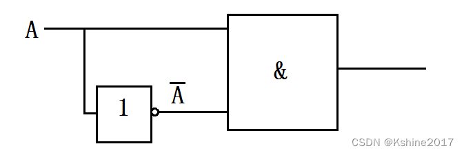
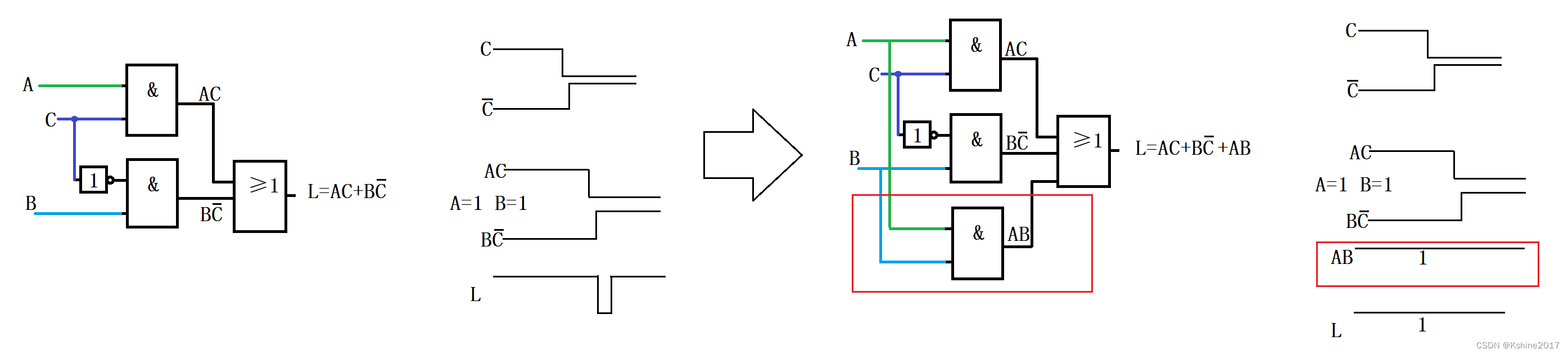
L = A ‾ ⋅ C ‾ + A ⋅ B = A ‾ ⋅ B ‾ ⋅ C ‾ + A ‾ ⋅ B ⋅ C ‾ + A ⋅ B ⋅ C ‾ + ABC = m 0 + m 2 + m 6 + m 7 L=A·B =A·B·C+A·B·C+A·B·C+A·B·C+ABC = m_0+m_2+m_6+m_7yo=A⋅C+A⋅B=A⋅B⋅C+A⋅B⋅C+A⋅B⋅C+Aantes de Cristo=metroetroetroetroetroetroetroetroetroetroetroetroetroetroetroetroetroetroetroetroetroetroetroetroetroetroetroetroetroetroetroetroetroetroetroetroetroetroetroetroetroetroetroetroetroetroetroetroetroetroetroetro0+metroetroetroetroetroetroetroetroetroetroetroetroetroetroetroetroetroetroetroetroetroetroetroetroetroetroetroetroetroetroetroetroetroetroetroetroetroetroetroetroetroetroetroetroetroetroetroetroetroetroetroetro2+metroetroetroetroetroetroetroetroetroetroetroetroetroetroetroetroetroetroetroetroetroetroetroetroetroetroetroetroetroetroetroetroetroetroetroetroetroetroetroetroetroetroetroetroetroetroetroetroetroetroetroetro6+metroetroetroetroetroetroetroetroetroetroetroetroetroetroetroetroetroetroetroetroetroetroetroetroetroetroetroetroetroetroetroetroetroetroetroetroetroetroetroetroetroetroetroetroetroetroetroetroetroetroetroetro7
Y 0 ‾ = E 3 ⋅ E 2 ‾ ‾ ⋅ E 1 ‾ ‾ ⋅ A 2 ‾ ⋅ A 1 ‾ ⋅ A 0 ‾ ‾ = E 3 ⋅ E 2 ‾ ‾ ⋅ E 1 ‾ ‾ ⋅ m 0 ‾ línea superior{Y_0} = línea superior{E_3·línea superior{línea superior{E_2}}·línea superior{línea superior{E_1}}·línea superior{A_2}·línea superior{A_1}·línea superior{A_0}} = línea superior{E_3·línea superior{línea superior{E_2}}·línea superior{línea superior{E_1}}·m_0}Y0=mi3⋅mi2⋅mi1⋅A2⋅A1⋅A0=mi3⋅mi2⋅mi1⋅metroetroetroetroetroetroetroetroetroetroetroetroetroetroetroetroetroetroetroetroetroetroetroetroetroetroetroetroetroetroetroetroetroetroetroetroetroetroetroetroetroetroetroetroetroetroetroetroetroetroetroetro0 //000
Y 1 ‾ = E 3 ⋅ E 2 ‾ ‾ ⋅ E 1 ‾ ‾ ⋅ A 2 ‾ ⋅ A 1 ‾ ⋅ A 0 ‾ = E 3 ⋅ E 2 ‾ ‾ ⋅ E 1 ‾ ‾ ⋅ m 1 ‾ línea superior{Y_1} = línea superior{E_3·línea superior{línea superior{E_2}}·línea superior{línea superior{E_1}}·línea superior{A_2}·línea superior{A_1}·A_0} = línea superior{E_3·línea superior{línea superior{E_2}}·línea superior{línea superior{E_1}}·m_1}Y1=mi3⋅mi2⋅mi1⋅A2⋅A1⋅A0=mi3⋅mi2⋅mi1⋅metroetroetroetroetroetroetroetroetroetroetroetroetroetroetroetroetroetroetroetroetroetroetroetroetroetroetroetroetroetroetroetroetroetroetroetroetroetroetroetroetroetroetroetroetroetroetroetroetroetroetroetro1 //001
Y 2 ‾ = E 3 ⋅ E 2 ‾ ‾ ⋅ E 1 ‾ ‾ ⋅ A 2 ‾ ⋅ A 1 ⋅ A 0 ‾ ‾ = E 3 ⋅ E 2 ‾ ‾ ⋅ E 1 ‾ ‾ ⋅ m 2 ‾ línea superior{Y_2} = línea superior{E_3·línea superior{línea superior{E_2}}·línea superior{línea superior{E_1}}·línea superior{A_2}·A_1·línea superior{A_0}}= línea superior{E_3·línea superior{línea superior{E_2}}·línea superior{línea superior{E_1}}·m_2}Y2=mi3⋅mi2⋅mi1⋅A2⋅A1⋅A0=mi3⋅mi2⋅mi1⋅metroetroetroetroetroetroetroetroetroetroetroetroetroetroetroetroetroetroetroetroetroetroetroetroetroetroetroetroetroetroetroetroetroetroetroetroetroetroetroetroetroetroetroetroetroetroetroetroetroetroetroetro2 //010
Y 3 ‾ = E 3 ⋅ E 2 ‾ ‾ ⋅ E 1 ‾ ‾ ⋅ A 2 ‾ ⋅ A 1 ⋅ A 0 ‾ = E 3 ⋅ E 2 ‾ ‾ ⋅ E 1 ‾ ‾ ⋅ m 3 ‾ línea superior{Y_3} = línea superior{E_3·línea superior{línea superior{E_2}}·línea superior{línea superior{E_1}}·línea superior{A_2}·A_1·A_0}= línea superior{E_3·línea superior{línea superior{E_2}}·línea superior{línea superior{E_1}}·m_3}Y3=mi3⋅mi2⋅mi1⋅A2⋅A1⋅A0=mi3⋅mi2⋅mi1⋅metroetroetroetroetroetroetroetroetroetroetroetroetroetroetroetroetroetroetroetroetroetroetroetroetroetroetroetroetroetroetroetroetroetroetroetroetroetroetroetroetroetroetroetroetroetroetroetroetroetroetroetro3 //011
Y 4 ‾ = E 3 ⋅ E 2 ‾ ‾ ⋅ E 1 ‾ ‾ ⋅ A 2 ⋅ A 1 ‾ ⋅ A 0 ‾ ‾ = E 3 ⋅ E 2 ‾ ‾ ⋅ E 1 ‾ ‾ ⋅ m 4 ‾ línea superior{Y_4} = línea superior{E_3·línea superior{línea superior{E_2}}·línea superior{línea superior{E_1}}·A_2·línea superior{A_1}·línea superior{A_0}}= línea superior{E_3·línea superior{línea superior{E_2}}·línea superior{línea superior{E_1}}·m_4}Y4=mi3⋅mi2⋅mi1⋅A2⋅A1⋅A0=mi3⋅mi2⋅mi1⋅metroetroetroetroetroetroetroetroetroetroetroetroetroetroetroetroetroetroetroetroetroetroetroetroetroetroetroetroetroetroetroetroetroetroetroetroetroetroetroetroetroetroetroetroetroetroetroetroetroetroetroetro4 //100
Y 5 ‾ = E 3 ⋅ E 2 ‾ ‾ ⋅ E 1 ‾ ‾ ⋅ A 2 ⋅ A 1 ‾ ⋅ A 0 ‾ = E 3 ⋅ E 2 ‾ ‾ ⋅ E 1 ‾ ‾ ⋅ m 5 ‾ línea superior{Y_5} = línea superior{E_3·línea superior{línea superior{E_2}}·línea superior{línea superior{E_1}}·A_2·línea superior{A_1}·A_0}= línea superior{E_3·línea superior{línea superior{E_2}}·línea superior{línea superior{E_1}}·m_5}Y5=mi3⋅mi2⋅mi1⋅A2⋅A1⋅A0=mi3⋅mi2⋅mi1⋅metroetroetroetroetroetroetroetroetroetroetroetroetroetroetroetroetroetroetroetroetroetroetroetroetroetroetroetroetroetroetroetroetroetroetroetroetroetroetroetroetroetroetroetroetroetroetroetroetroetroetroetro5 //101
Y 6 ‾ = E 3 ⋅ E 2 ‾ ‾ ⋅ E 1 ‾ ‾ ⋅ A 2 ⋅ A 1 ⋅ A 0 ‾ ‾ = E 3 ⋅ E 2 ‾ ‾ ⋅ E 1 ‾ ‾ ⋅ m 6 ‾ línea superior{Y_6} = línea superior{E_3·línea superior{línea superior{E_2}}·línea superior{línea superior{E_1}}·A_2·A_1·línea superior{A_0}}= línea superior{E_3·línea superior{línea superior{E_2}}·línea superior{línea superior{E_1}}·m_6}Y6=mi3⋅mi2⋅mi1⋅A2⋅A1⋅A0=mi3⋅mi2⋅mi1⋅metroetroetroetroetroetroetroetroetroetroetroetroetroetroetroetroetroetroetroetroetroetroetroetroetroetroetroetroetroetroetroetroetroetroetroetroetroetroetroetroetroetroetroetroetroetroetroetroetroetroetroetro6 //110
Y 7 ‾ = E 3 ⋅ E 2 ‾ ‾ ⋅ E 1 ‾ ‾ ⋅ A 2 ⋅ A 1 ⋅ A 0 ‾ = E 3 ⋅ E 2 ‾ ‾ ⋅ E 1 ‾ ‾ ⋅ m 7 ‾ línea superior{Y_7} = línea superior{E_3·línea superior{línea superior{E_2}}·línea superior{línea superior{E_1}}·A_2·A_1·A_0}= línea superior{E_3·línea superior{línea superior{E_2}}·línea superior{línea superior{E_1}}·m_7}Y7=mi3⋅mi2⋅mi1⋅A2⋅A1⋅A0=mi3⋅mi2⋅mi1⋅metroetroetroetroetroetroetroetroetroetroetroetroetroetroetroetroetroetroetroetroetroetroetroetroetroetroetroetroetroetroetroetroetroetroetroetroetroetroetroetroetroetroetroetroetroetroetroetroetroetroetroetro7 //111
Asegúrese de que E 3 = 1, E 2 = 0, E 1 = 0 Asegúrese de que E_3 = 1, E_2 = 0, E_1 = 0Cerciorarsemi3=1,mi2=0,mi1=0, es decir Y 0 ‾ = m 0 ‾ , Y 2 ‾ = m 2 ‾ , Y 6 ‾ = m 6 ‾ , Y 7 ‾ = m 7 ‾ línea superior{Y_0}=línea superior{m_0}, línea superior{Y_2}=línea superior{m_2}, línea superior{Y_6}=línea superior{m_6}, línea superior{Y_7}=línea superior{m_7}Y0=metroetroetroetroetroetroetroetroetroetroetroetroetroetroetroetroetroetroetroetroetroetroetroetroetroetroetroetroetroetroetroetroetroetroetroetroetroetroetroetroetroetroetroetroetroetroetroetroetroetroetroetro0,Y2=metroetroetroetroetroetroetroetroetroetroetroetroetroetroetroetroetroetroetroetroetroetroetroetroetroetroetroetroetroetroetroetroetroetroetroetroetroetroetroetroetroetroetroetroetroetroetroetroetroetroetroetro2,Y6=metroetroetroetroetroetroetroetroetroetroetroetroetroetroetroetroetroetroetroetroetroetroetroetroetroetroetroetroetroetroetroetroetroetroetroetroetroetroetroetroetroetroetroetroetroetroetroetroetroetroetroetro6,Y7=metroetroetroetroetroetroetroetroetroetroetroetroetroetroetroetroetroetroetroetroetroetroetroetroetroetroetroetroetroetroetroetroetroetroetroetroetroetroetroetroetroetroetroetroetroetroetroetroetroetroetroetro7。
Transformar funciones lógicas según la ley de inversión.
L = L ‾ ‾ = m 0 + m 2 + m 6 + m 7 ‾ ‾ = m 0 ‾ ⋅ m 2 ‾ ⋅ m 6 ‾ ⋅ m 7 ‾ ‾ = m 0 + m 2 + m 6 + m 7 ‾ ‾ = Y 0 ‾ ⋅ Y 2 ‾ ⋅ Y 6 ‾ ⋅ Y 7 ‾ ‾ L=línea superior{línea superior{L}} = línea superior{línea superior{m_0+m_2+m_6+m_7}} = línea superior{línea superior{m_0}·línea superior{m_2}·línea superior{m_6}·línea superior{m_7}} = sobrelínea{sobrelínea{m_0+m_2+m_6+m_7}} = sobrelínea{sobrelínea{Y_0}·sobrelínea{Y_2}·sobrelínea{Y_6}·sobrelínea{Y_7}}yo=yo=metroetroetroetroetroetroetroetroetroetroetroetroetroetroetroetroetroetroetroetroetroetroetroetroetroetroetroetroetroetroetroetroetroetroetroetroetroetroetroetroetroetroetroetroetroetroetroetroetroetroetroetro0+metroetroetroetroetroetroetroetroetroetroetroetroetroetroetroetroetroetroetroetroetroetroetroetroetroetroetroetroetroetroetroetroetroetroetroetroetroetroetroetroetroetroetroetroetroetroetroetroetroetroetroetro2+metroetroetroetroetroetroetroetroetroetroetroetroetroetroetroetroetroetroetroetroetroetroetroetroetroetroetroetroetroetroetroetroetroetroetroetroetroetroetroetroetroetroetroetroetroetroetroetroetroetroetroetro6+metroetroetroetroetroetroetroetroetroetroetroetroetroetroetroetroetroetroetroetroetroetroetroetroetroetroetroetroetroetroetroetroetroetroetroetroetroetroetroetroetroetroetroetroetroetroetroetroetroetroetroetro7=metroetroetroetroetroetroetroetroetroetroetroetroetroetroetroetroetroetroetroetroetroetroetroetroetroetroetroetroetroetroetroetroetroetroetroetroetroetroetroetroetroetroetroetroetroetroetroetroetroetroetroetro0⋅metroetroetroetroetroetroetroetroetroetroetroetroetroetroetroetroetroetroetroetroetroetroetroetroetroetroetroetroetroetroetroetroetroetroetroetroetroetroetroetroetroetroetroetroetroetroetroetroetroetroetroetro2⋅metroetroetroetroetroetroetroetroetroetroetroetroetroetroetroetroetroetroetroetroetroetroetroetroetroetroetroetroetroetroetroetroetroetroetroetroetroetroetroetroetroetroetroetroetroetroetroetroetroetroetroetro6⋅metroetroetroetroetroetroetroetroetroetroetroetroetroetroetroetroetroetroetroetroetroetroetroetroetroetroetroetroetroetroetroetroetroetroetroetroetroetroetroetroetroetroetroetroetroetroetroetroetroetroetroetro7=metroetroetroetroetroetroetroetroetroetroetroetroetroetroetroetroetroetroetroetroetroetroetroetroetroetroetroetroetroetroetroetroetroetroetroetroetroetroetroetroetroetroetroetroetroetroetroetroetroetroetroetro0+metroetroetroetroetroetroetroetroetroetroetroetroetroetroetroetroetroetroetroetroetroetroetroetroetroetroetroetroetroetroetroetroetroetroetroetroetroetroetroetroetroetroetroetroetroetroetroetroetroetroetroetro2+metroetroetroetroetroetroetroetroetroetroetroetroetroetroetroetroetroetroetroetroetroetroetroetroetroetroetroetroetroetroetroetroetroetroetroetroetroetroetroetroetroetroetroetroetroetroetroetroetroetroetroetro6+metroetroetroetroetroetroetroetroetroetroetroetroetroetroetroetroetroetroetroetroetroetroetroetroetroetroetroetroetroetroetroetroetroetroetroetroetroetroetroetroetroetroetroetroetroetroetroetroetroetroetroetro7=Y0⋅Y2⋅Y6⋅Y7
Obtener diagrama lógico

774HC42
4 entradas
10 terminales de salida, la salida está activa a un nivel bajo, correspondiente a los números decimales del 0 al 9.

4 terminales de entrada, un total de 16 situaciones
solo m0, m1, m2...m9m_0,m_1,m_2......m_9metroetroetroetroetroetroetroetroetroetroetroetroetroetroetroetroetroetroetroetroetroetroetroetroetroetroetroetroetroetroetroetroetroetroetroetroetroetroetroetroetroetroetroetroetroetroetroetroetroetroetroetro0,metroetroetroetroetroetroetroetroetroetroetroetroetroetroetroetroetroetroetroetroetroetroetroetroetroetroetroetroetroetroetroetroetroetroetroetroetroetroetroetroetroetroetroetroetroetroetroetroetroetroetroetro1,metroetroetroetroetroetroetroetroetroetroetroetroetroetroetroetroetroetroetroetroetroetroetroetroetroetroetroetroetroetroetroetroetroetroetroetroetroetroetroetroetroetroetroetroetroetroetroetroetroetroetroetro2......metroetroetroetroetroetroetroetroetroetroetroetroetroetroetroetroetroetroetroetroetroetroetroetroetroetroetroetroetroetroetroetroetroetroetroetroetroetroetroetroetroetroetroetroetroetroetroetroetroetroetroetro9Es una entrada válida (el pin de salida correspondiente emite 0 bajo y las otras salidas son 1 alto).
Entre los 6 restantes m10, m11, m12... m15 m_{10}, m_{11}, m_{12}...... m_{15}metroetroetroetroetroetroetroetroetroetroetroetroetroetroetroetroetroetroetroetroetroetroetroetroetroetroetroetroetroetroetroetroetroetroetroetroetroetroetroetroetroetroetroetroetroetroetroetroetroetroetroetro10,metroetroetroetroetroetroetroetroetroetroetroetroetroetroetroetroetroetroetroetroetroetroetroetroetroetroetroetroetroetroetroetroetroetroetroetroetroetroetroetroetroetroetroetroetroetroetroetroetroetroetroetro11,metroetroetroetroetroetroetroetroetroetroetroetroetroetroetroetroetroetroetroetroetroetroetroetroetroetroetroetroetroetroetroetroetroetroetroetroetroetroetroetroetroetroetroetroetroetroetroetroetroetroetroetro12......metroetroetroetroetroetroetroetroetroetroetroetroetroetroetroetroetroetroetroetroetroetroetroetroetroetroetroetroetroetroetroetroetroetroetroetroetroetroetroetroetroetroetroetroetroetroetroetroetroetroetroetro15Significa que no hay una salida de decodificación válida (cuando no es válida, la salida es 1 alta).
Dibuje los diagramas de forma de onda de entrada y salida del 74HC42.


Principio de visualización del tubo digital

Decodificador de display integrado de siete segmentos. 74HC4511 (cátodo común) (el nivel alto se ilumina)
EL ELyomiHabilitación de pestillo
LT ‾ línea superior{LT}yoyoentrada de prueba de lámpara cuando LT ‾ = 0 línea superior{LT}=0yoyo=0Cuando , ag genera todo 1 y muestra la fuente "8".
BL ‾ línea superior{BL}ByoEntrada de luz apagada, cuando LT ‾ = 1 y BL ‾ = 1 sobre línea {LT} = 1 y sobre línea {BL} = 1yoyo=1,yByo=1 Cuando , todas las salidas son 0. Se puede utilizar para apagar el cero "0" innecesario que se muestra.

D3D2D1D0 D_3D_2D_1D_0D3D2D1D0=0000, el glifo de salida correspondiente "0"
D3D2D1D0 D_3D_2D_1D_0D3D2D1D0=0001, la fuente de salida correspondiente "1"
D3D2D1D0 D_3D_2D_1D_0D3D2D1D0=0010, la fuente de salida correspondiente "2"
D3D2D1D0 D_3D_2D_1D_0D3D2D1D0=0011, la fuente de salida correspondiente "3"
D3D2D1D0 D_3D_2D_1D_0D3D2D1D0=0100, la fuente de salida correspondiente "4"
D3D2D1D0 D_3D_2D_1D_0D3D2D1D0=0101, la fuente de salida correspondiente "5"
D3D2D1D0 D_3D_2D_1D_0D3D2D1D0=0110, la fuente de salida correspondiente "6"
D3D2D1D0 D_3D_2D_1D_0D3D2D1D0=0111, la fuente de salida correspondiente "7"
D3D2D1D0 D_3D_2D_1D_0D3D2D1D0=1000, la fuente de salida correspondiente "8"
D3D2D1D0 D_3D_2D_1D_0D3D2D1D0=1001, la fuente de salida correspondiente "9"
1010-1111, apagado
De uno a muchos, los datos de la línea de datos común se envían a diferentes canales según sea necesario.
Similar al "interruptor multipolar unipolar"
Utilizando un decodificador de dirección único, implemente el asignador de datos.
Por ejemplo, 74x138 integra un decodificador de 3 a 8 líneas.
E 1 ‾ como entrada de datos sobre línea{E_1} como entrada de datosmi1como entrada de datos
Y0 Y1 Y2 Y3 Y4 Y5 Y6 Y7 Y_0 Y_1 Y_2Y_3Y_4Y_5Y_6Y_7Y0Y1Y2Y3Y4Y5Y6Y78 canales como salida de datos

Y 2 ‾ = E 3 ⋅ E 2 ‾ ‾ ⋅ E 1 ‾ ‾ ⋅ A 2 ‾ ⋅ A 1 ⋅ A 0 ‾ ‾ línea superior{Y_2} = línea superior{E_3·línea superior{línea superior{E_2}}·línea superior{línea superior{E_1}}·línea superior{A_2}·A_1·línea superior{A_0}}Y2=mi3⋅mi2⋅mi1⋅A2⋅A1⋅A0 //010
En la foto de arriba, E 3 = 1, E 2 ‾ = 0 E_3=1, línea superior{E_2}=0mi3=1,mi2=0, cuando la línea de dirección Un 2 Un 1 Un 0 = 010 Un_2A_1A_0=010A2A1A0=010hora, Y 2 ‾ = E 1 ‾ línea superior{Y_2}=línea superior{E_1}Y2=mi1
De la misma manera podemos concluir:
Cuando la línea de dirección Un 2 Un 1 Un 0 = 000 Un_2A_1A_0=000A2A1A0=000hora, Y 0 ‾ = E 1 ‾ = D línea superior{Y_0}=línea superior{E_1}=DY0=mi1=D,otro Y x = 1 Y_x=1YX=1。
Cuando la línea de dirección Un 2 Un 1 Un 0 = 001 Un_2Un_1Un_0=001A2A1A0=001hora, Y 1 ‾ = E 1 ‾ = D línea superior{Y_1}=línea superior{E_1}=DY1=mi1=D,otro Y x = 1 Y_x=1YX=1。
Cuando la línea de dirección Un 2 Un 1 Un 0 = 010 Un_2A_1A_0=010A2A1A0=010hora, Y 2 ‾ = E 1 ‾ = D línea superior{Y_2}=línea superior{E_1}=DY2=mi1=D,otro Y x = 1 Y_x=1YX=1。
Cuando la línea de dirección Un 2 Un 1 Un 0 = 011 Un_2A_1A_0=011A2A1A0=011hora, Y 3 ‾ = E 1 ‾ = D línea superior{Y_3}=línea superior{E_1}=DY3=mi1=D,otro Y x = 1 Y_x=1YX=1。
Cuando la línea de dirección Un 2 Un 1 Un 0 = 100 Un_2A_1A_0=100A2A1A0=100hora, Y 4 ‾ = E 1 ‾ = D línea superior{Y_4}=línea superior{E_1}=DY4=mi1=D,otro Y x = 1 Y_x=1YX=1。
Cuando la línea de dirección Un 2 Un 1 Un 0 = 101 Un_2Un_1Un_0=101A2A1A0=101hora, Y 5 ‾ = E 1 ‾ = D línea superior{Y_5}=línea superior{E_1}=DY5=mi1=D,otro Y x = 1 Y_x=1YX=1。
Cuando la línea de dirección Un 2 Un 1 Un 0 = 110 Un_2Un_1Un_0=110A2A1A0=110hora, Y 6 ‾ = E 1 ‾ = D línea superior{Y_6}=línea superior{E_1}=DY6=mi1=D,otro Y x = 1 Y_x=1YX=1。
Cuando la línea de dirección Un 2 Un 1 Un 0 = 111 Un_2Un_1Un_0=111A2A1A0=111hora, Y 7 ‾ = E 1 ‾ = D línea superior{Y_7}=línea superior{E_1}=DY7=mi1=D,otro Y x = 1 Y_x=1YX=1。

Y = S2‾⋅S1‾⋅S0‾⋅D0 + S2‾⋅S1‾⋅S0⋅D1 + S2‾⋅S1⋅S0‾⋅D2 + S2‾⋅S1⋅S0⋅D3 + S2⋅S1‾⋅S0‾⋅D4 + S2⋅S1‾⋅S0⋅D5 + S2⋅S1⋅S0‾⋅D6 + S2⋅S1⋅S0 ⋅ D 7 Y=sobrelínea{S_2}·sobrelínea{S_1}·sobrelínea{S_0}·D_0 +sobrelínea{S_2}·sobrelínea{S_1}·S_0·D_1 +sobrelínea{S_2}·S_1·sobrelínea{S_0}·D_2 +sobrelínea{S_2}·S_1·S_0·D_3 +S_2·sobrelínea{S_1}·sobrelínea{S_0}·D_4 +S_2·sobrelínea{S_1}·S_0·D_5 +S_2·S_1·sobrelínea{S_0}·D_6 +S_2·S_1·S_0·D_7Y=S2⋅S1⋅S0⋅D0+S2⋅S1⋅S0⋅D1+S2⋅S1⋅S0⋅D2+S2⋅S1⋅S0⋅D3+S2⋅S1⋅S0⋅D4+S2⋅S1⋅S0⋅D5+S2⋅S1⋅S0⋅D6+S2⋅S1⋅S0⋅D7

Extensiones para selectores de datos.
generador de funciones lógicas
Selector de datos conocido de 8 a 1.
Y = S2‾⋅S1‾⋅S0‾⋅D0 + S2‾⋅S1‾⋅S0⋅D1 + S2‾⋅S1⋅S0‾⋅D2 + S2‾⋅S1⋅S0⋅D3 + S2⋅S1‾⋅S0‾⋅D4 + S2⋅S1‾⋅S0⋅D5 + S2⋅S1⋅S0‾⋅D6 + S2⋅S1⋅S0 ⋅ D 7 Y=sobrelínea{S_2}·sobrelínea{S_1}·sobrelínea{S_0}·D_0 +sobrelínea{S_2}·sobrelínea{S_1}·S_0·D_1 +sobrelínea{S_2}·S_1·sobrelínea{S_0}·D_2 +sobrelínea{S_2}·S_1·S_0·D_3 +S_2·sobrelínea{S_1}·sobrelínea{S_0}·D_4 +S_2·sobrelínea{S_1}·S_0·D_5 +S_2·S_1·sobrelínea{S_0}·D_6 +S_2·S_1·S_0·D_7Y=S2⋅S1⋅S0⋅D0+S2⋅S1⋅S0⋅D1+S2⋅S1⋅S0⋅D2+S2⋅S1⋅S0⋅D3+S2⋅S1⋅S0⋅D4+S2⋅S1⋅S0⋅D5+S2⋅S1⋅S0⋅D6+S2⋅S1⋅S0⋅D7
Y = m0⋅D0 + m1⋅D1 + m2⋅D2 + m3⋅D3 + m4⋅D4 + m5⋅D5 + m6⋅D6 + m7⋅D7 Y=m_0·D_0 +m_1·D_1 +m_2·D_2 +m_3·D_3 +m_4·D_4 +m_5·D_5 +m_6·D_6 +m_7·D_7Y=metroetroetroetroetroetroetroetroetroetroetroetroetroetroetroetroetroetroetroetroetroetroetroetroetroetroetroetroetroetroetroetroetroetroetroetroetroetroetroetroetroetroetroetroetroetroetroetroetroetroetroetro0⋅D0+metroetroetroetroetroetroetroetroetroetroetroetroetroetroetroetroetroetroetroetroetroetroetroetroetroetroetroetroetroetroetroetroetroetroetroetroetroetroetroetroetroetroetroetroetroetroetroetroetroetroetroetro1⋅D1+metroetroetroetroetroetroetroetroetroetroetroetroetroetroetroetroetroetroetroetroetroetroetroetroetroetroetroetroetroetroetroetroetroetroetroetroetroetroetroetroetroetroetroetroetroetroetroetroetroetroetroetro2⋅D2+metroetroetroetroetroetroetroetroetroetroetroetroetroetroetroetroetroetroetroetroetroetroetroetroetroetroetroetroetroetroetroetroetroetroetroetroetroetroetroetroetroetroetroetroetroetroetroetroetroetroetroetro3⋅D3+metroetroetroetroetroetroetroetroetroetroetroetroetroetroetroetroetroetroetroetroetroetroetroetroetroetroetroetroetroetroetroetroetroetroetroetroetroetroetroetroetroetroetroetroetroetroetroetroetroetroetroetro4⋅D4+metroetroetroetroetroetroetroetroetroetroetroetroetroetroetroetroetroetroetroetroetroetroetroetroetroetroetroetroetroetroetroetroetroetroetroetroetroetroetroetroetroetroetroetroetroetroetroetroetroetroetroetro5⋅D5+metroetroetroetroetroetroetroetroetroetroetroetroetroetroetroetroetroetroetroetroetroetroetroetroetroetroetroetroetroetroetroetroetroetroetroetroetroetroetroetroetroetroetroetroetroetroetroetroetroetroetroetro6⋅D6+metroetroetroetroetroetroetroetroetroetroetroetroetroetroetroetroetroetroetroetroetroetroetroetroetroetroetroetroetroetroetroetroetroetroetroetroetroetroetroetroetroetroetroetroetroetroetroetroetroetroetroetro7⋅D7
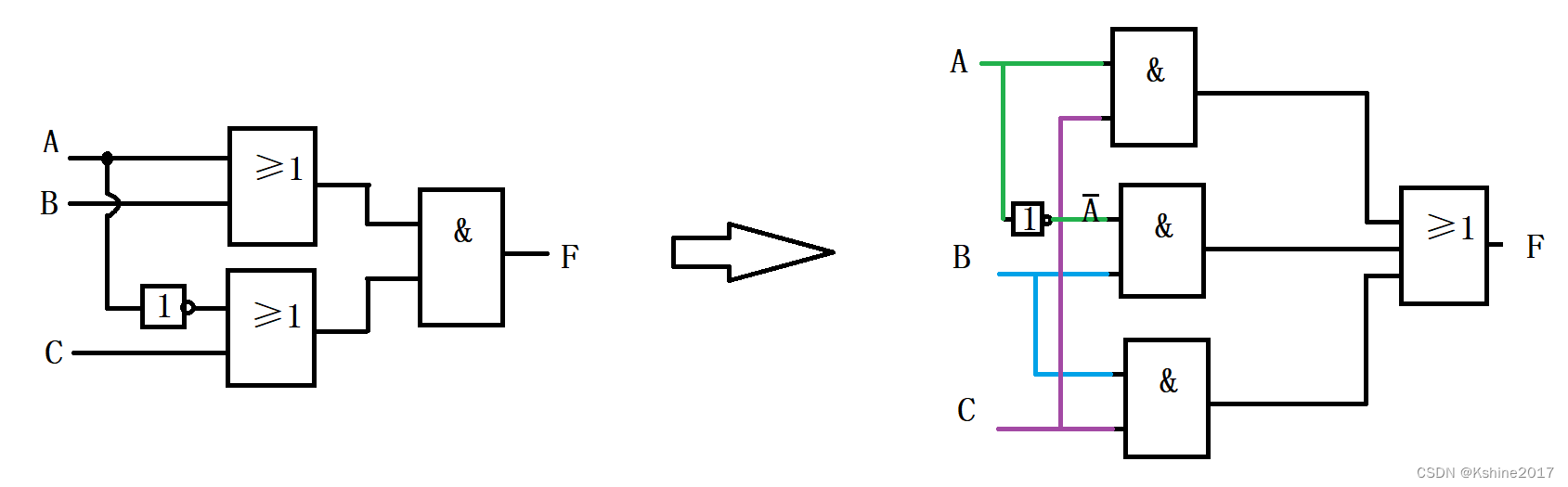
función lógica L = A ‾ BC + AB ‾ C + ABL=sobrelínea{A}BC+Asobrelínea{B}C+AByo=Aantes de Cristo+ABC+AB
L = A ‾ BC + AB ‾ C + AB = A ‾ BC + AB ‾ C + ABC ‾ + ABC = m 3 + m 5 + m 6 + m 7 L=sobrelínea{A}BC+Asobrelínea{B}C+AB=sobrelínea{A}BC+Asobrelínea{B}C+ABsobrelínea{C}+ABC=m_3+m_5+m_6+m_7yo=Aantes de Cristo+ABC+AB=Aantes de Cristo+ABC+ABC+Aantes de Cristo=metroetroetroetroetroetroetroetroetroetroetroetroetroetroetroetroetroetroetroetroetroetroetroetroetroetroetroetroetroetroetroetroetroetroetroetroetroetroetroetroetroetroetroetroetroetroetroetroetroetroetroetro3+metroetroetroetroetroetroetroetroetroetroetroetroetroetroetroetroetroetroetroetroetroetroetroetroetroetroetroetroetroetroetroetroetroetroetroetroetroetroetroetroetroetroetroetroetroetroetroetroetroetroetroetro5+metroetroetroetroetroetroetroetroetroetroetroetroetroetroetroetroetroetroetroetroetroetroetroetroetroetroetroetroetroetroetroetroetroetroetroetroetroetroetroetroetroetroetroetroetroetroetroetroetroetroetroetro6+metroetroetroetroetroetroetroetroetroetroetroetroetroetroetroetroetroetroetroetroetroetroetroetroetroetroetroetroetroetroetroetroetroetroetroetroetroetroetroetroetroetroetroetroetroetroetroetroetroetroetroetro7
Utilice el selector de datos 8 a 1 para implementar la función L anterior
L = Y = m 3 + m 5 + m 6 + m 7 , donde D 7 D 6 D 5 D 3 = 1111 , D 4 D 2 D 1 D 0 = 0000 L=Y=m_3+m_5+m_6+m_7, Entre ellos D_7D_6D_5D_3=1111, D_4D_2D_1D_0=0000yo=Y=metroetroetroetroetroetroetroetroetroetroetroetroetroetroetroetroetroetroetroetroetroetroetroetroetroetroetroetroetroetroetroetroetroetroetroetroetroetroetroetroetroetroetroetroetroetroetroetroetroetroetroetro3+metroetroetroetroetroetroetroetroetroetroetroetroetroetroetroetroetroetroetroetroetroetroetroetroetroetroetroetroetroetroetroetroetroetroetroetroetroetroetroetroetroetroetroetroetroetroetroetroetroetroetroetro5+metroetroetroetroetroetroetroetroetroetroetroetroetroetroetroetroetroetroetroetroetroetroetroetroetroetroetroetroetroetroetroetroetroetroetroetroetroetroetroetroetroetroetroetroetroetroetroetroetroetroetroetro6+metroetroetroetroetroetroetroetroetroetroetroetroetroetroetroetroetroetroetroetroetroetroetroetroetroetroetroetroetroetroetroetroetroetroetroetroetroetroetroetroetroetroetroetroetroetroetroetroetroetroetroetro7,enD7D6D5D3=1111,D4D2D1D0=0000

Datos paralelos a datos en serie

| A | B | FA > B FA > BFA>B | FA < B FAFA<B | FA = = B F_{A==B}FA==B |
|---|---|---|---|---|
| 0 | 0 | 0 | 0 | 1 |
| 0 | 1 | 0 | 1 | 0 |
| 1 | 0 | 1 | 0 | 0 |
| 1 | 1 | 0 | 0 | 1 |

| ¿Un 1? B 1 ¿Un _1? B_1A1?B1 | A0?B0A_0?B_0A0?B0 | FA > B FA > BFA>B | FA < B FAFA<B | FA = = B F_{A==B}FA==B |
|---|---|---|---|---|
| A1>B1 A_1>B_1A1>B1 | X | 1 | 0 | 0 |
| A1 < B1 A_1A1<B1 | X | 0 | 1 | 0 |
| A1 = = B1 A_1==B_1A1==B1 | A0>B0A_0>B_0A0>B0 | 1 | 0 | 0 |
| A1 = = B1 A_1==B_1A1==B1 | A0 < B0 A_0A0<B0 | 0 | 1 | 0 |
| A1 = = B1 A_1==B_1A1==B1 | A0 = = B0 A_0==B_0A0==B0 | 0 | 0 | 1 |
expresión lógica
FA > B = FA 1 > B 1 + FA 1 = = B 1 ⋅ FA 0 > B 0 F_{A>B} = F_{A_1>B_1} +F_{A_1==B_1}·F_{A_0>B_0}FA>B=FA1>B1+FA1==B1⋅FA0>B0
FA < B = FA 1 < B 1 + FA 1 = = B 1 ⋅ FA 0 < B 0 F_{AFA<B=FA1<B1+FA1==B1⋅FA0<B0
FA = = B = FA 1 = = B 1 ⋅ FA 0 = = B 0 F_{A==B} = F_{A_1==B_1}·F_{A_0==B_0}FA==B=FA1==B1⋅FA0==B0
diagrama de lógica


Conexión en serie, ampliada a comparador numérico de 8 bits

Conexión paralela, ampliada a comparador numérico de 16 bits.
Cuando se conecta en paralelo, la velocidad es rápida.


Se ha dedicado a la investigación de tecnología durante más de 30 años y domina varios lenguajes como java, linux, javascript, php, css, etc. Ha realizado muchas contribuciones en el campo del código abierto. Estación de documentación para desarrolladores para compartir algunos problemas en el desarrollo de tecnología para referencia futura.

Correo[email protected]